
System and method for pivotal installation and removal of a circuit board from a chassis

a technology of circuit board and chassis, which is applied in the direction of electrical apparatus casing/cabinet/drawer, coupling device connection, instruments, etc., can solve the problems of increasing difficulty in removing and installing circuit boards, increasing the height of the device in the rack, and increasing the difficulty of removal and installation of circuit boards

Inactive Publication Date: 2005-11-29
VALTRUS INNOVATIONS LTD
View PDF7 Cites 15 Cited by
  • Summary
  • Abstract
  • Description
  • Claims
  • Application Information

AI Technical Summary

Problems solved by technology

The physical constraints of the device also may make removal and installation of the circuit board difficult and / or time consuming.
This gets increasingly difficult as the weight and the height of the device in the rack increases.
The process of removing and reinstalling the mid-plane board is time-consuming.

Method used


Image

  • System and method for pivotal installation and removal of a circuit board from a chassis
  • System and method for pivotal installation and removal of a circuit board from a chassis
  • System and method for pivotal installation and removal of a circuit board from a chassis

Examples


Embodiment Construction

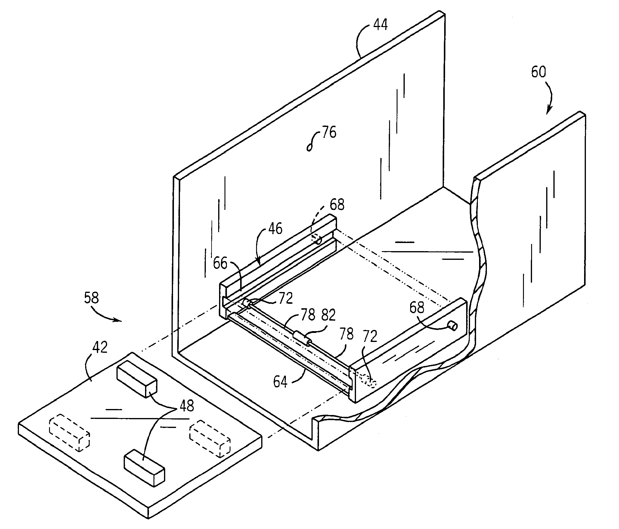
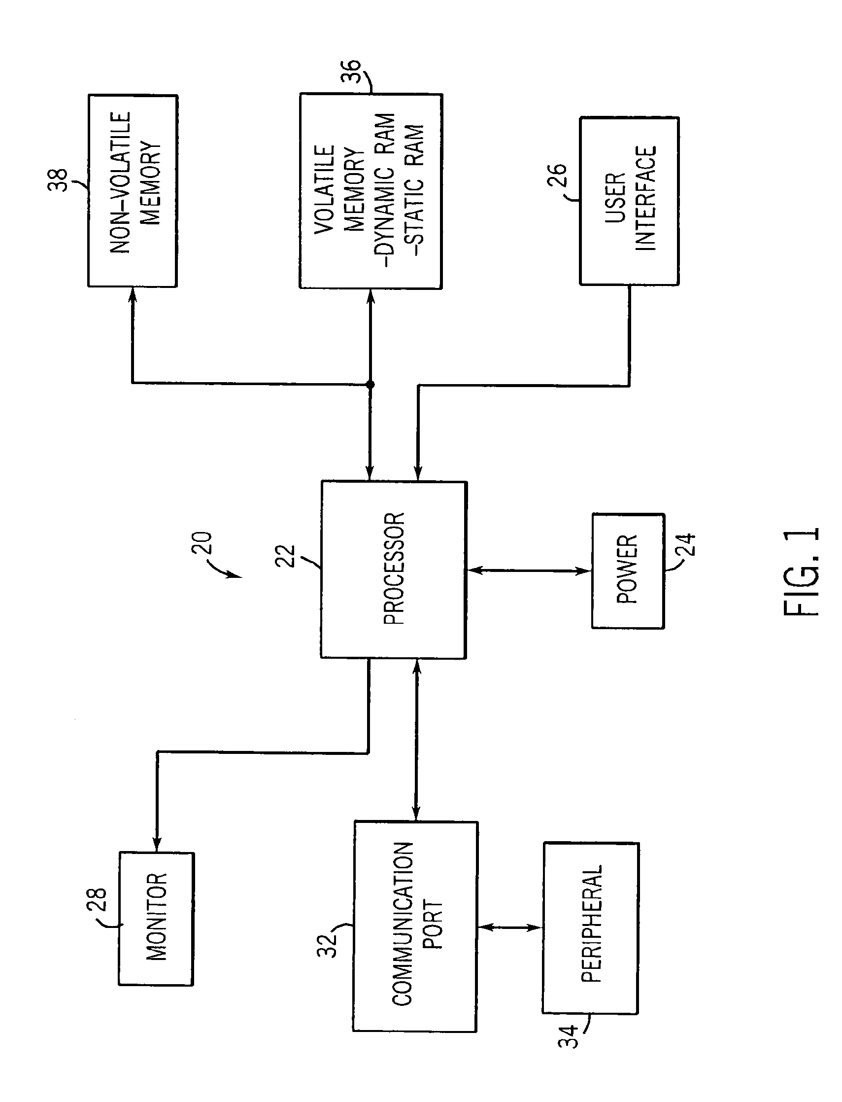
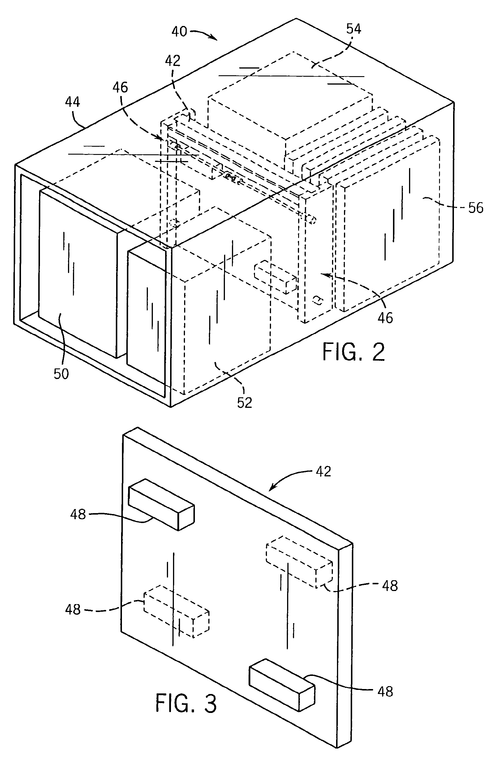
[0025]Referring generally to FIG. 1, a block diagram is illustrated depicting an exemplary processor-based device, generally designated by the reference numeral 20. The processor-based device 20 may be any of a variety of different devices, such as a personal computer or a server.

[0026]The illustrated processor-based device 20 uses a processor 22 to control the operation of the device 20. The processor 22 may be a microprocessor, such as used in a personal computer, or other type of processor. The illustrated processor-based device 20 has a power supply 24 to supply power to the other components of the system. Various additional components of system 20 may be coupled to the processor 22. For instance, a user interface 26 may be coupled to the processor 22 to allow an operator to control some or all of the functions of the device. Examples of user interfaces include a keyboard, a mouse, or a joystick. A monitor 28 may be coupled to the processor 22 to allow an operator to view visual...


PUM


Abstract

A multi-sectional computing device configurable for a plurality of computing worlds, including portable and desktop computing worlds. The technique includes a space saving and configuration technique utilizing multiple joints disposed between multiple sections to facilitate rotational orientation of the sections to adjust for space limitations and other characteristics of a desired environment or computing world. The multiple sections include a display assembly and a housing assembly for computing components.

Description

CROSS REFERENCE TO RELATED APPLICATION(s);[0001]This is a continuation of application Ser. No. 10 / 041,010 filed on Jan. 7, 2002, now U.S. Pat. No. 6,667,889 which is hereby incorporated by reference herein.FIELD OF THE INVENTION[0002]The present invention relates generally to a system and method for installing printed circuit boards into an electronic device, and particularly to a device for guiding and retaining a printed circuit board in an electronic device.BACKGROUND OF THE INVENTION[0003]Printed circuit boards, otherwise known as boards or cards, serve as a basic framework for assembling electrical components into a useful electronic device. In a typical electronic device, electronic components are mounted onto a surface of the board. Metal lead wires from the component are then soldered to conductive traces on the board. Soldering the leads to the board serves two purposes: first, it secures the electronic component to the printed circuit board and, second, it ensures a good e...

Claims


Application Information

Patent Timeline
Patent Type & Authority Patents(United States)
IPC IPC(8): H05K7/16
CPCH05K7/16
Inventor JANSEN, KENNETH A.
Owner VALTRUS INNOVATIONS LTD
Learn More