Multipoint lock system

a multi-point lock and lock technology, applied in the field of door locks, can solve the problems of multiple locks, requiring additional time and effort on the part of the operator to lock or unlock, and one lock member being engaged

Inactive Publication Date: 2005-12-06
TRUTH HARDWARE
View PDF10 Cites 85 Cited by
  • Summary
  • Abstract
  • Description
  • Claims
  • Application Information

AI Technical Summary

Benefits of technology

[0009]The present invention is directed to an apparatus that satisfies the needs set forth above by providing an improved multipoint lock system. A multipoint lock system having features of the present invention comprises a first lock mechanism having a deployed and retracted condition and a second lock mechanism having an open and blocked condition. The system is designed so that the first lock mechanism engages the second lock mechanism via a set of locking points when the second lock mechanism is in the open condition and the first lock mechanism is prevented from engaging the second lock mechanism when the second lock mechanism is in the blocked condition. The system also allows for the incorporation of a unique multi-tiered actuator system into the first lock mechanism, which provides this mechanism with an automatic locking function and a manual locking function. Key to the automatic locking function is a sensor-trigger unit, whereby at least one sensor-trigger mechanism attached to the first lock mechanism and having at least one sensor-trigger contacts at least one sensor pad attached to the second lock mechanism allowing the first lock mechanism to automatically engage the second lock mechanism. Should the automatic locking function fail, the manual locking function allows a user to manually engage the first lock mechanism with the second lock mechanism.

Problems solved by technology

Multiple locks, however, require additional time and effort on the part of an operator to lock or unlock them, but provide the greater security.
In some cases, the multiple lock members are designed for independent actuation, with the unfortunate result that frequently only one of the lock members is engaged due to human forgetfulness and / or neglect.
In other designs, the multiple lock members are adapted for concurrent actuation from a single actuator lever or handle, but these systems have tended to be difficult to assemble and install in a cost effective manner, especially if the door frame requires the addition of an astragal.
Additionally, many of the conventional multipoint lock systems do not address the problem of accidental lockouts and accidental damage to the doorframe when the user attempts to force open an active door, which is assumed to be unlocked.

Method used


Image

  • Multipoint lock system
  • Multipoint lock system
  • Multipoint lock system

Examples


Embodiment Construction

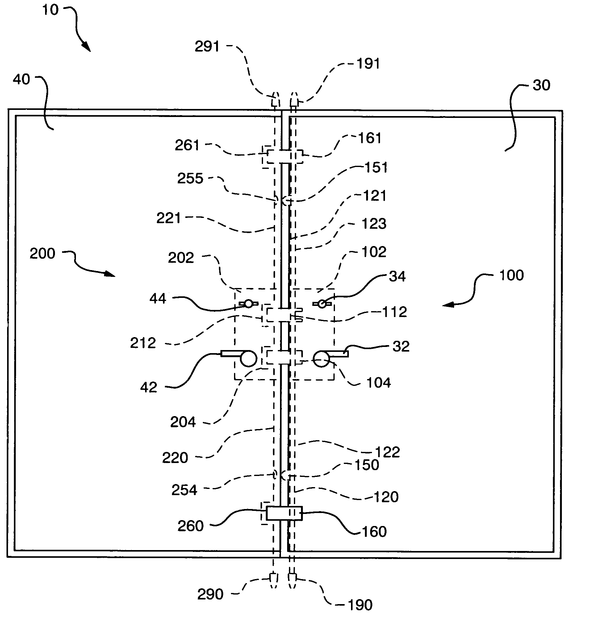
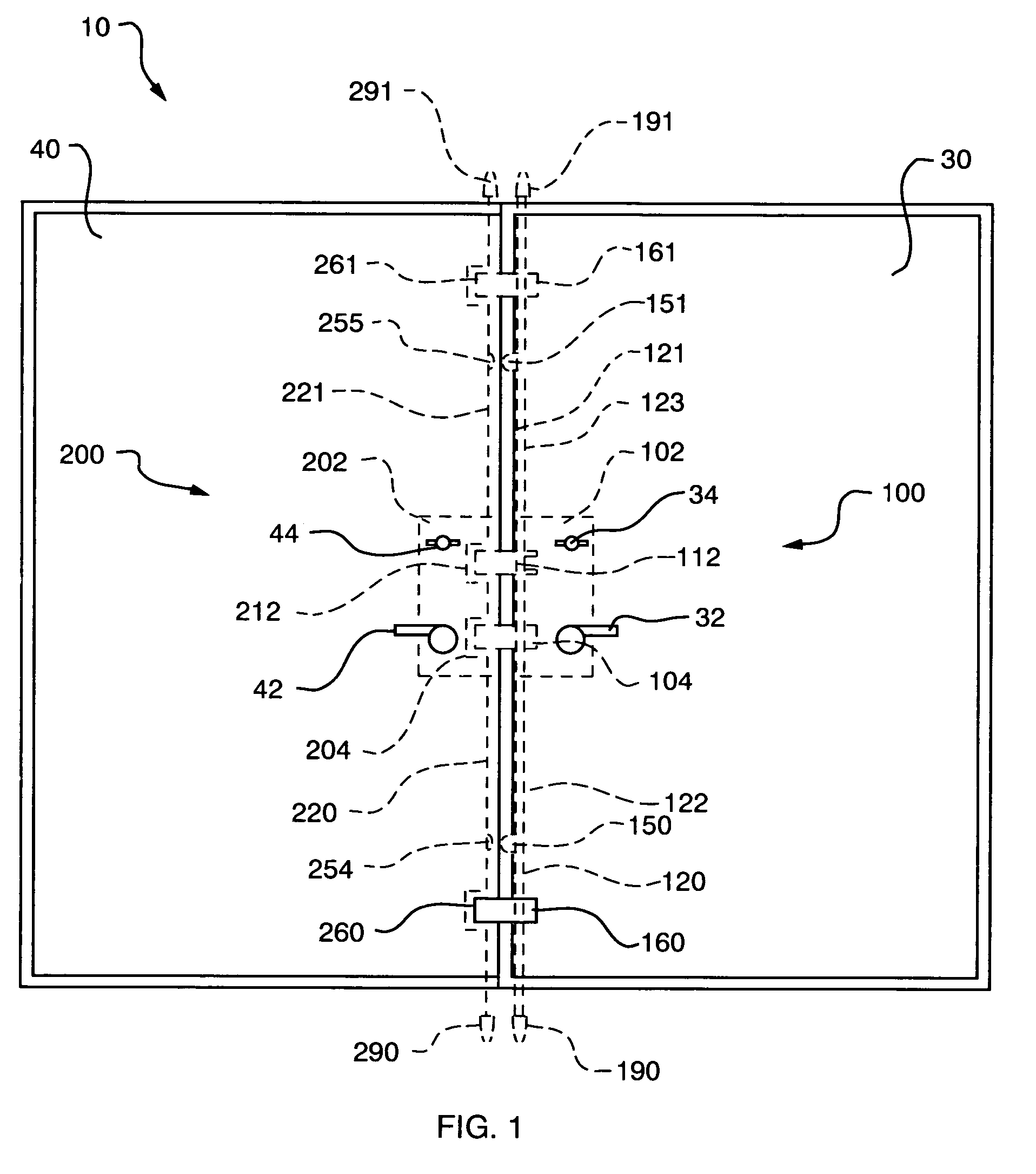
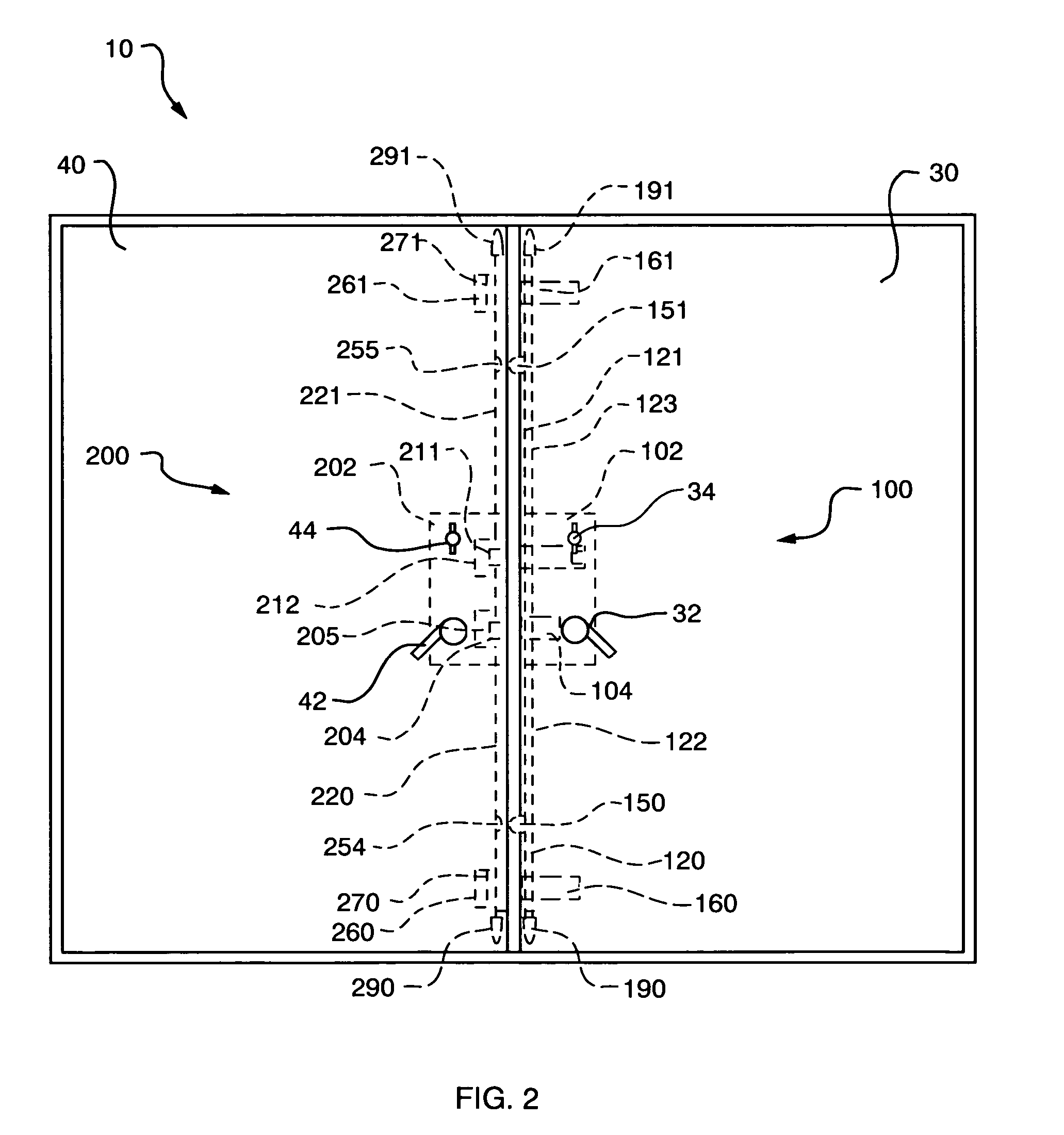
[0049]At the outset, the invention is described in its broadest overall aspects with a more detailed description following. Essentially, the invention, a multipoint lock system, comprises a first lock mechanism and a second lock mechanism, the second lock mechanism having an open condition and a blocked condition, wherein the first lock mechanism engages the second lock mechanism when the second lock mechanism is in the open condition, and wherein the first lock mechanism is prevented from engaging the second lock mechanism when the second lock mechanism is in the blocked condition. In sum, when the first and second lock mechanisms are engaged, the members (e.g., doors) to which these mechanisms are attached are locked in a closed position.

[0050]Referring to FIGS. 1–2, a multipoint lock system 10, which is adaptable to swinging and sliding two-door sets and other door applications including but not limited to single swinging doors and sliding doors, is shown in the locked condition ...


PUM


Abstract

A multipoint lock system for use with the active and inactive doors of two-door sets, which provides an operator with the ability to lock or unlock a plurality of locking points both manually and automatically, and features a blocking mechanism to prevent unwanted locking. The system comprises a pair of releasably engaged mechanisms, one of which primarily controls the deployment of the locking members, while the other primarily controls the receiving windows that receive the locking members. Each mechanism is operated by a lever and thumbturn attached to a centralized cassette.

Description

CROSS-REFERENCE TO RELATED APPLICATIONS[0001]This application is the national stage of International Application No. PCT / US01 / 45585, filed Oct. 19, 2001 and published in English under PCT Article 21(2), which claims the benefit of U.S. Provisional Application Nos. 60 / 241,683, filed Oct. 19, 2000, and 60 / 241,684, filed Oct. 19, 2000, the contents of which are incorporated by reference herein.BACKGROUND OF THE INVENTION[0002](1) Field of the Invention[0003]The present invention relates generally to door locks and more specifically to an improved multipoint door lock system for controlling locking and unlocking of the inactive and active doors of a two-door set.[0004](2) Description of the Related Art[0005]Many patio or other entryways utilize two swinging or sliding doors that meet in the middle of the doorway as opposed to a single door. When a two-door configuration is used, one door is referred to as the active door and the other is referred to as the inactive door. The active door...

Claims


Application Information

Patent Timeline
Patent Type & Authority Patents(United States)
IPC IPC(8): E05B1/00E05B63/00E05B63/20E05C7/04E05C9/04E05C9/12E05C9/18
CPCE05B63/20E05C7/04E05C9/041E05B63/0065E05B2001/0076E05C9/1841E05C9/1883Y10S292/21Y10T292/0843Y10T292/0993Y10T292/1018Y10T292/54
Inventor BECKEN, DONALD A.
Owner TRUTH HARDWARE
Why Eureka
Try Eureka