Zero insertion force electrical connector

a technology of electrical connectors and zero insertion force, which is applied in the direction of coupling contact members, coupling device connections, coupling parts engagement/disengagement, etc., can solve the problem that the zif connector b>9/b> cannot provide reliable electrical connection between the connection member and the pcb

Inactive Publication Date: 2005-12-06
HON HAI PRECISION IND CO LTD
View PDF12 Cites 21 Cited by
  • Summary
  • Abstract
  • Description
  • Claims
  • Application Information

AI Technical Summary

Problems solved by technology

When this happens, the ZIF connector 9 cannot provide reliable electrical connection between the connection member and the PCB.

Method used


Image

  • Zero insertion force electrical connector
  • Zero insertion force electrical connector
  • Zero insertion force electrical connector

Examples


Embodiment Construction

[0021]Reference will now be made to the drawings to describe the present invention in detail.

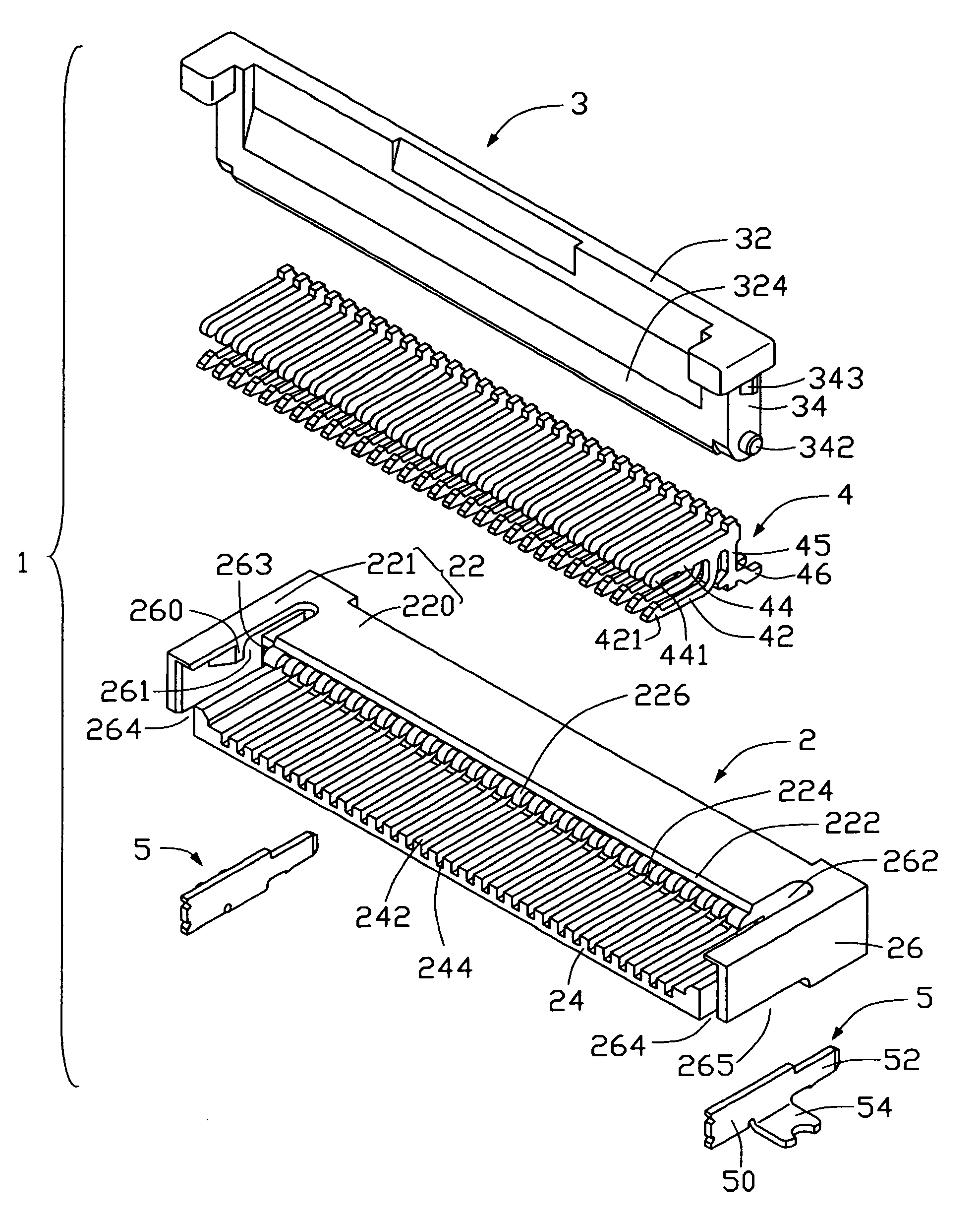
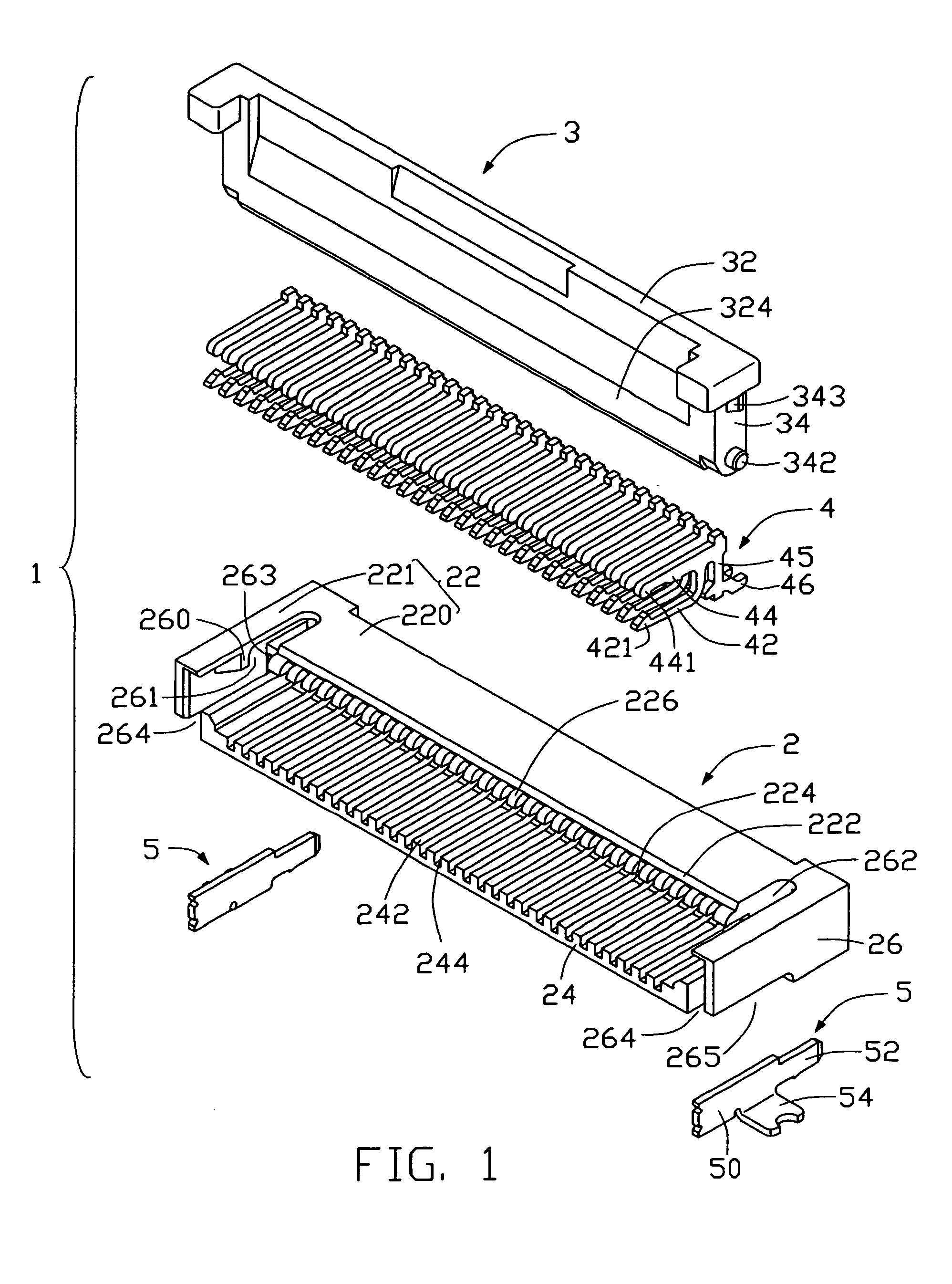
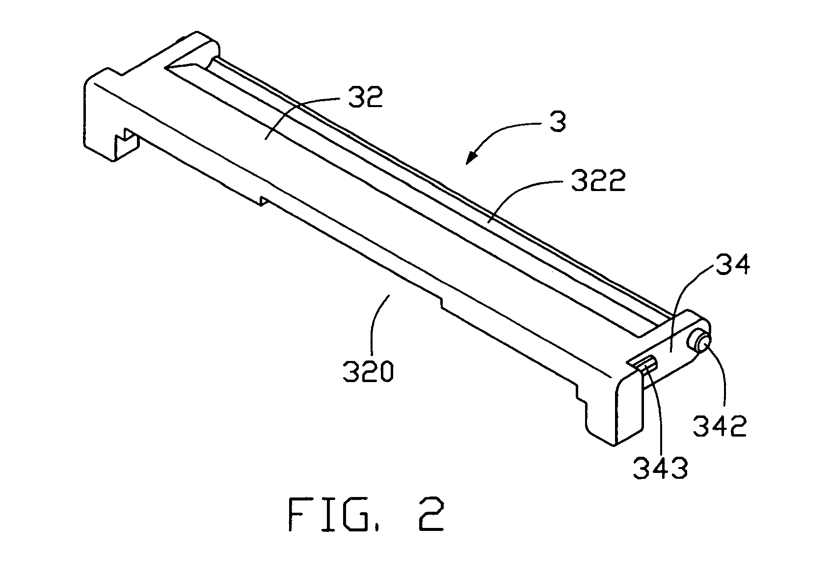
[0022]FIG. 1 is an exploded, isometric view of a zero insertion force (ZIF) electrical connector 1 of the preferred embodiment of the present invention. The connector 1 provides electrical connection between a sheet-like connection member (not shown) such as a flexible circuit board (PCB) or a flat cable with a circuit substrate such as a printed circuit board (PCB) (not shown). The connector 1 comprises an insulative housing 2, a plurality of electrical contacts 4 received in the housing 2, a rotatable operation member 3 mounted on the housing 2, and a pair of positioning members 5 mounted on two opposite ends of the housing 2 respectively.

[0023]The housing 2 comprises a lower wall 24, a pair of lateral sidewalls 26 respectively extending from two opposite ends of the lower wall 24, and an upper wall 22 interconnecting the sidewalls 26. The lower wall 24 forms a multiplicity of spaced first...


PUM


Abstract

An electrical connector (1) includes an insulative housing (2) for receiving a sheet-like connection member, a plurality of electrical contacts (4) received in the housing, and an operation member (3) mounted onto the housing. The housing has a lower wall (24) and an upper wall (22) opposite to the lower wall. The upper wall forms a plurality of second ribs on a bottom thereof. Each second rib forms a curved end (226) exposed outwardly from an edge (222) of the upper wall. The operation member forms an elongate pressing portion (324) at a bottom thereof, and a channel (322) defined in a main face thereof opposite from the pressing portion. The operation member is rotatable from an open position to a closed position, with the channel pivoting about the curved ends of the first ribs of the housing, thereby pressing the connection member upon the contact arms of the contacts.

Description

BACKGROUND OF THE INVENTION[0001]1. Field of the Invention[0002]The present invention relates to a zero insertion force electrical connector, which provides electrical connection between a sheet-like connection member such as a flexible printed circuit (FPC) or a flat cable with a circuit substrate such as a printed circuit board (PCB).[0003]2. Description of the Prior Art[0004]Zero insertion force (ZIF) electrical connectors are widely used for electrically connecting sheet-like connection members such as flexible printed circuits (FPCs) or flat cables with circuit substrates such as printed circuit boards (PCBs). Such ZIF connectors are disclosed in U.S. Pat. Nos. 5,695,360, 5,785,549, 5,842,883 and 5,895,287.[0005]FIG. 8 shows a cut-away view of a conventional ZIF connector 9. The ZIF connector 9 comprises an insulative housing 8, a plurality of electrical contacts 6 received in the housing 8, and a rotatable pressuring member 7 mounted on the housing 8. The housing 8 comprises a...

Claims


Application Information

Patent Timeline
Patent Type & Authority Patents(United States)
IPC IPC(8): H01R12/16H01R12/18
CPCH01R12/88H01R12/79
Inventor SHIU, GUO JIUNCHEN, KUN HUAWATANABE, SADAO
Owner HON HAI PRECISION IND CO LTD
Why Eureka
Try Eureka