Developing apparatus with two developing chamber-rotatable member pairs
a technology of rotating member and developing chamber, which is applied in the direction of electrographic process apparatus, instruments, optics, etc., can solve the problems of non-uniformity of image density or increase of mechanical deposition power of toner, affecting the development speed of toner, etc., to achieve the effect of preventing deterioration of the developer and prolonging the distance between n1
- Summary
- Abstract
- Description
- Claims
- Application Information
AI Technical Summary
Benefits of technology
Problems solved by technology
Method used
Image
Examples
embodiment 1
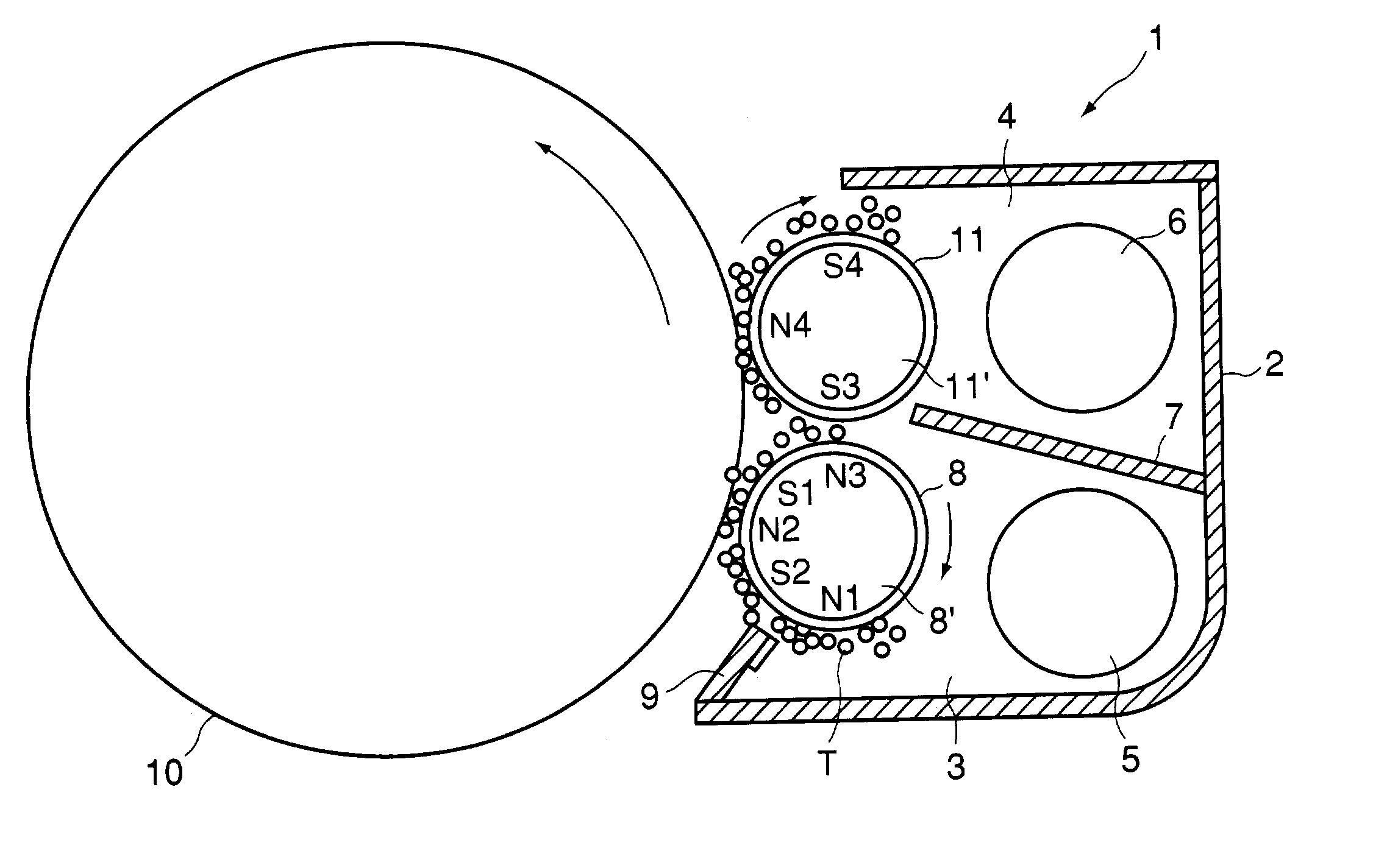
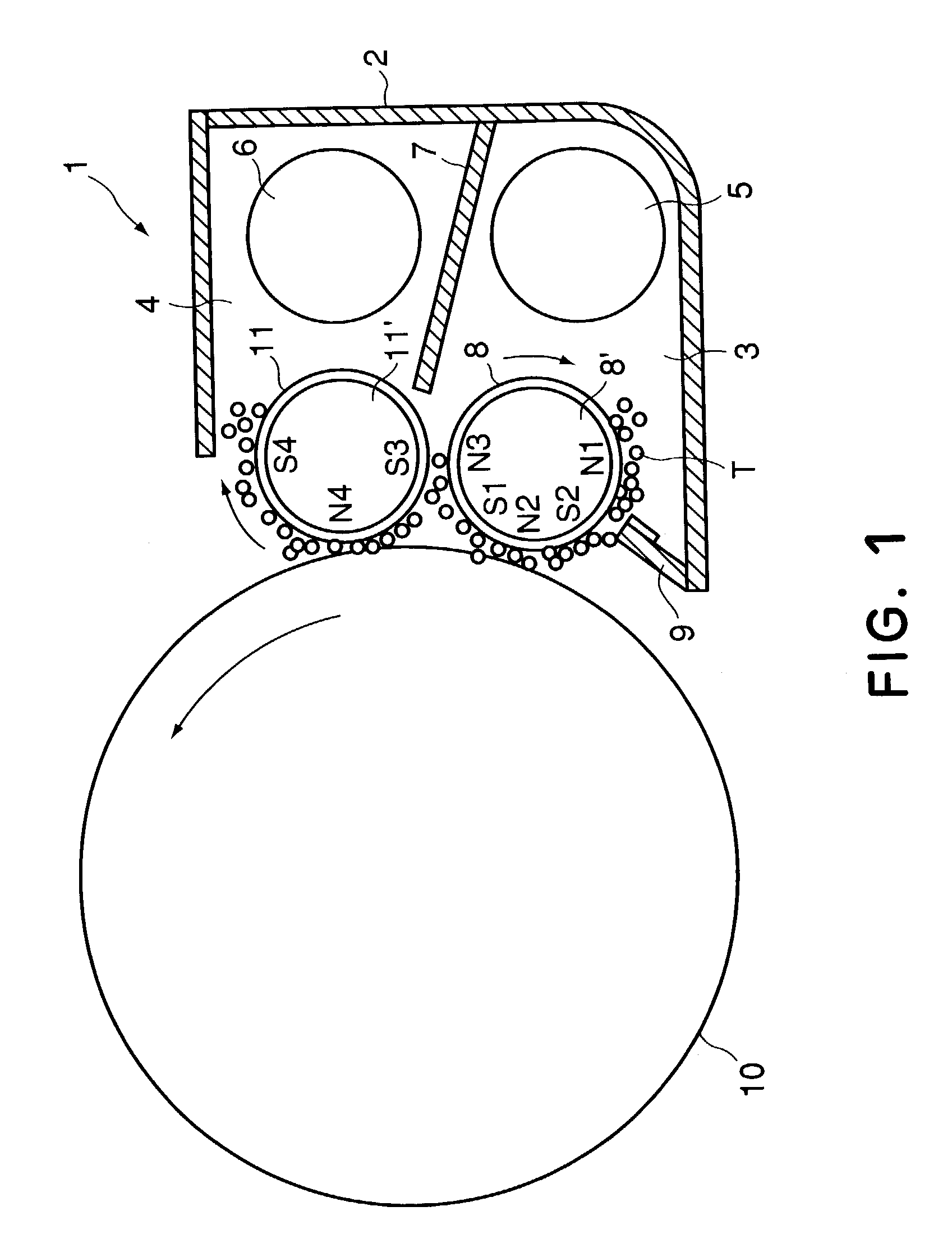
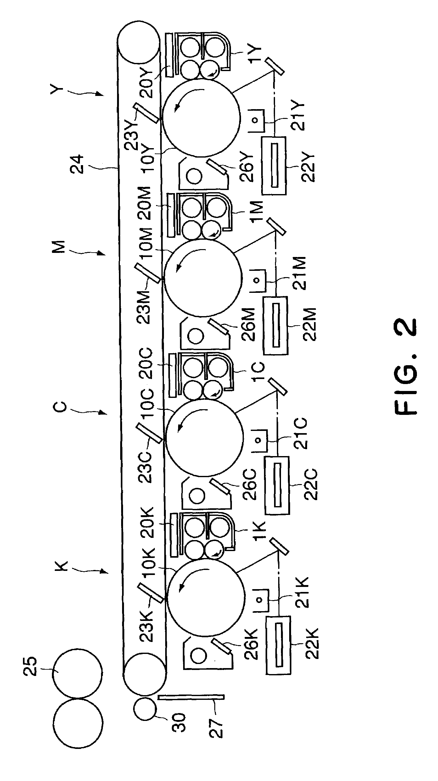
[0045]FIG. 1 shows a positional relation of the developing device 1 relative to image bearing member (photosensitive drum) 10 in each of Y, M, C, K image forming stations in a full-color image forming apparatus as shown in FIG. 2. The Y, M, C, K image forming stations have substantially the same structure, and they form yellow (Y), magenta (M), cyan (C) and black (K) images, respectively in a full-color image forming operation. In the following descriptions, when reference is made to “developing device 1”, it applies to a developing device in each of developing device 1Y, developing device 1M, developing device 1C and developing device 1K in the Y, M, C, K image forming stations.
[0046]Referring to FIG. 2, the operations of the entire image forming apparatus will be described.
[0047]The photosensitive drum 10 (image bearing member) is rotatably provided in image forming apparatus, the photosensitive drum 10 is uniformly charged by a primary charger 21 and is then exposed to light modu...
embodiment 2
[0069]Referring to FIG. 5 a developing device according to Embodiment 2 will be described.
[0070]The developing device of this embodiment is similar to that of Embodiment 1. However, in the developing device 100 of this embodiment, the regulating blade 9 is opposed to a neighborhood of a first magnetic pole N1 which is a downstream side magnetic pole of the first and second magnetic poles N1, N3 which are provided in the first developing sleeve and which form the repelling magnetic field with respect to the rotational direction of the developing sleeve 8, by which the regulation of the layer thickness for the developer is effected simultaneously with taking the developer up.
[0071]This arrangement per se is known as means with which the developing device torque can be significantly reduced as disclosed in Japanese Laid-open Patent Application Hei 11-194617. However, if this is used with a single developing sleeve structure or with the horizontal arrangement, the developer stagnating r...
embodiment 3
[0074]Referring to FIG. 6, Embodiment 3 of this invention will be described. FIG. 6 is and axial sectional view of the developing device 101 according to this embodiment.
[0075]The developing device of this embodiment has substantially the similar structure to the developing device 1 of Embodiment 1. However, in this embodiment, there is provided a discharge opening 12, in the outer wall adjacent a most downstream portion of the developer chamber 3 wall, for discharged the developer when the height of the surface level of the developer exceeds a predetermined level (indicated by g in the Figure).
[0076]When the developer T said by the feeding screw 5 in the developer chamber 3 is not taken up on the first developing sleeve 8 and is accumulated in the developer stagnation portion at the most downstream portion of the developer chamber 3, the surface level of the power of the developer rises. Even in such a case, the developer is automatically discharged through the developer discharge ...
PUM
 Abstract
Description
Claims
Application Information
 - R&D
- Intellectual Property
- Life Sciences
- Materials
- Tech Scout
- Unparalleled Data Quality
- Higher Quality Content
- 60% Fewer Hallucinations
Browse by: Latest US Patents, China's latest patents, Technical Efficacy Thesaurus, Application Domain, Technology Topic, Popular Technical Reports.
© 2025 PatSnap. All rights reserved.Legal|Privacy policy|Modern Slavery Act Transparency Statement|Sitemap|About US| Contact US: help@patsnap.com


