Pallet for surgical stapling cartridge

a technology of surgical staples and cartridges, applied in the field of methods and methods for loading surgical staples, can solve the problems of time and/or product loss

Inactive Publication Date: 2005-12-13
SCHNIPKE FAMILY LIABILITY
View PDF12 Cites 178 Cited by
  • Summary
  • Abstract
  • Description
  • Claims
  • Application Information

AI Technical Summary

Problems solved by technology

However, the mechanisms for this insertion require dexterity by trained people who are able to position the frames that contain the drivers and the cartridges, and actuate the machines to insert the tiny drivers into the precisely formed holes in the cartridges.
If any drivers are improperly inserted into a cartridge, or are not inserted, the cartridge is either discarded or repaired, which means that errors in insertion of the tiny parts can result in time and / or product lost.
Such problems in manufacturing occur due to human error, and therefore it is desirable to mechanize the process to reduce the number of opportunities for error.

Method used


Image

  • Pallet for surgical stapling cartridge
  • Pallet for surgical stapling cartridge
  • Pallet for surgical stapling cartridge

Examples


Embodiment Construction

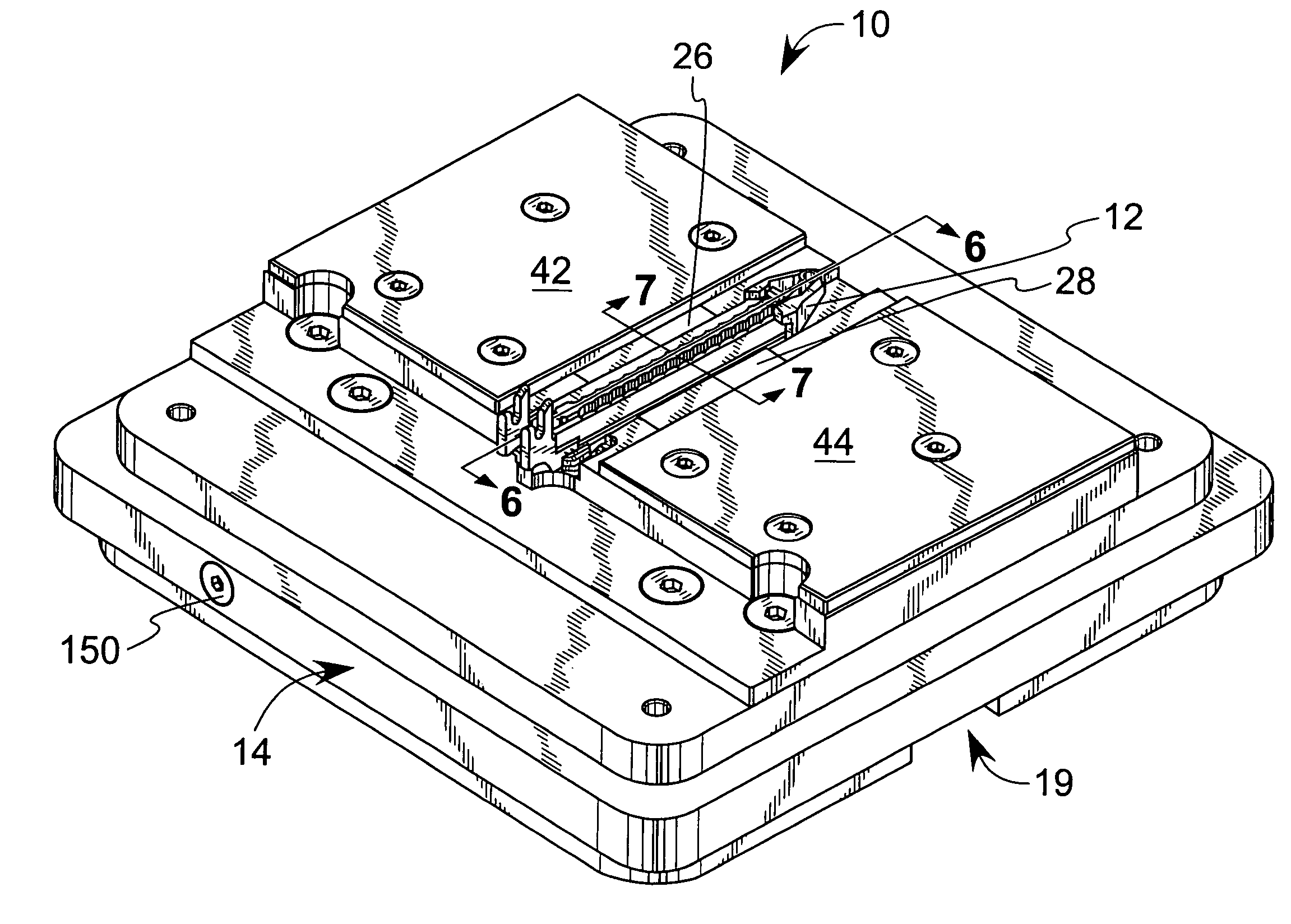
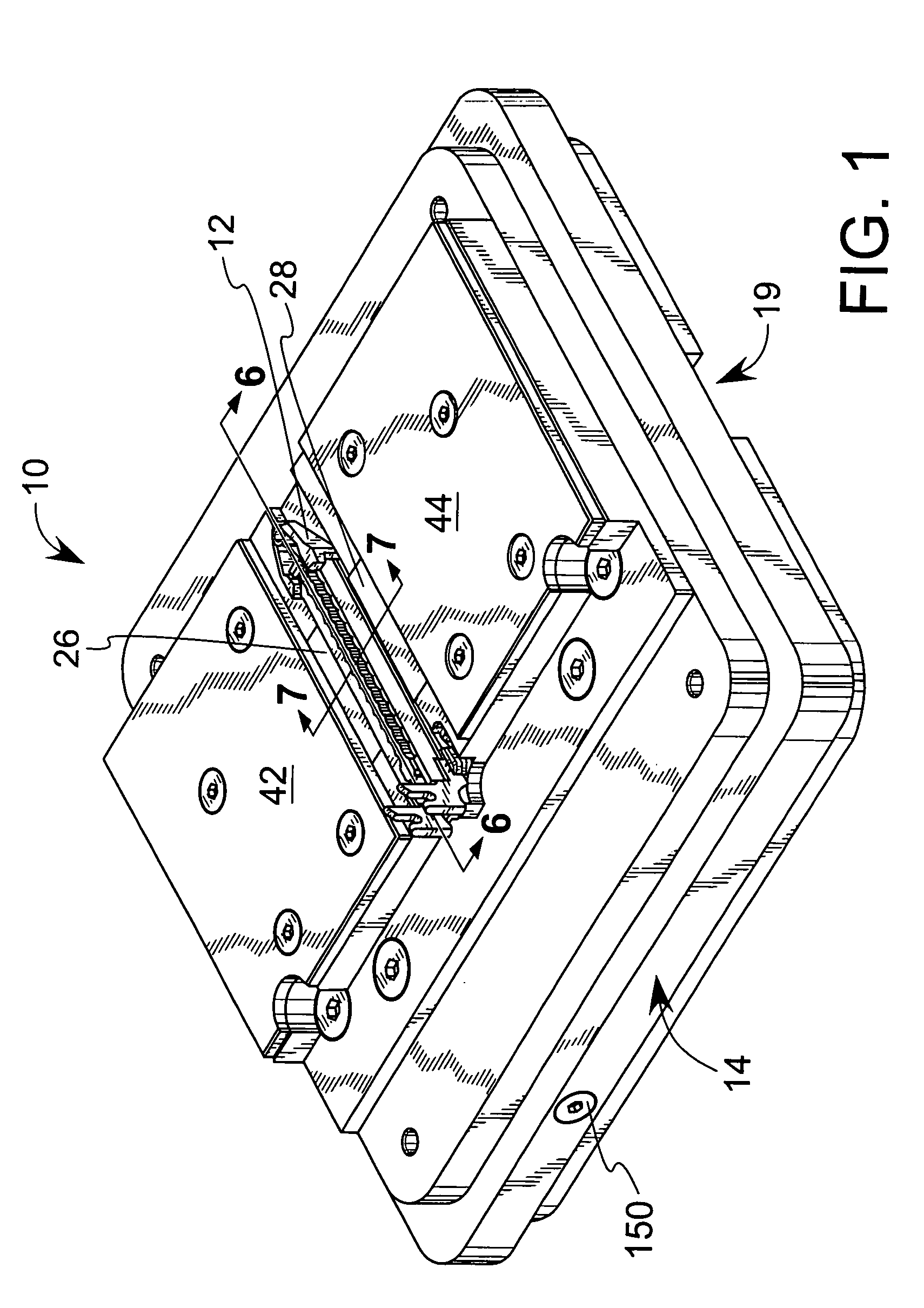
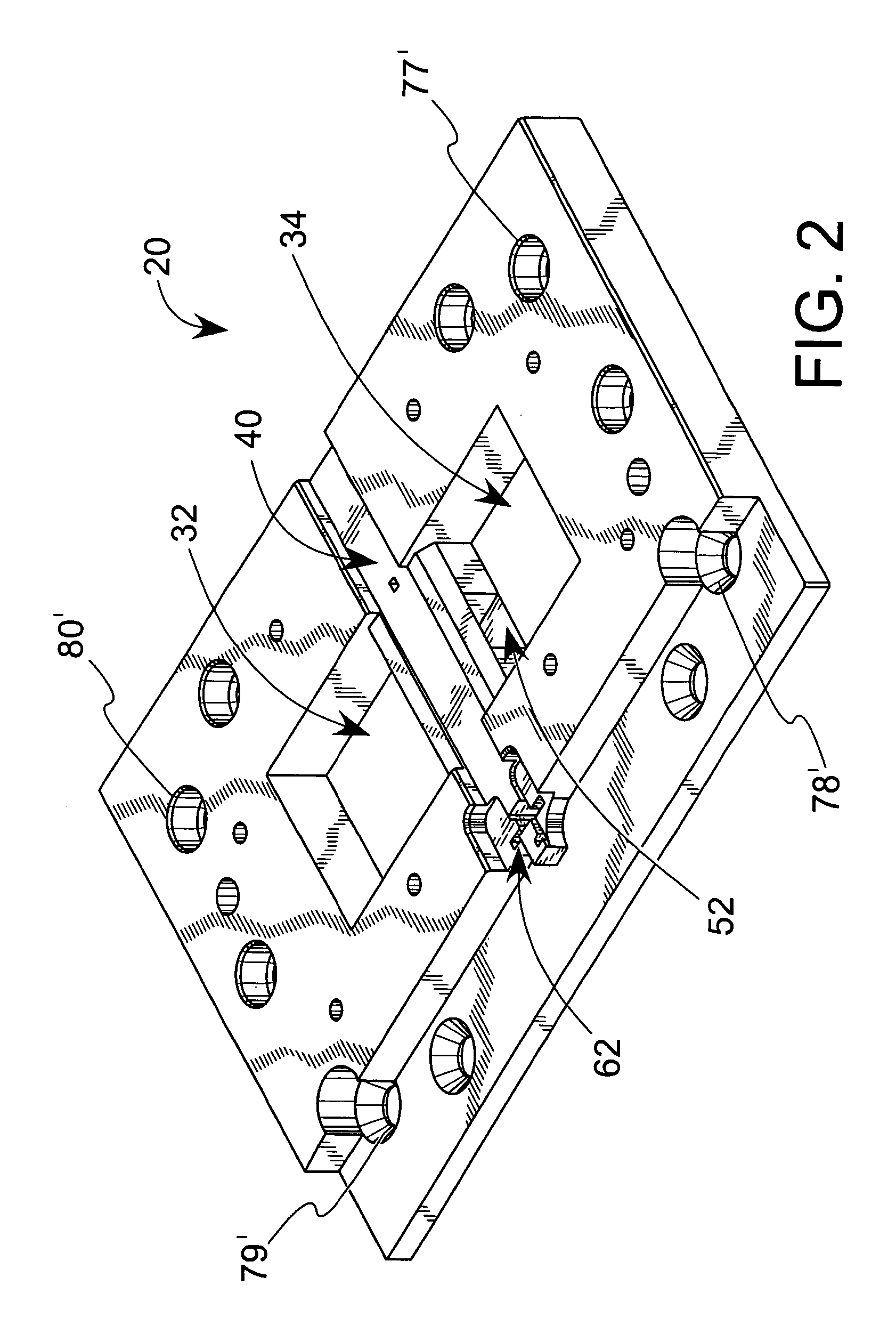
[0033]The preferred pallet 10 is shown in FIG. 1 with a surgical stapling cartridge 12 mounted therein in an operable position. The pallet 10 is essentially made up of two components: the cartridge holder 20 shown in FIG. 2, and the base 14 shown in FIGS. 3 and 4. The base 14 is made of two subcomponents: the plate 16 and the ring 18. The plate 16 and the components of the cartridge holder 20 are preferably made of steel. The plate 16 forms a rigid frame to which the other components of the pallet 10 attach. The ring 18 is preferably made of a low friction polymer, such as is sold in association with the trademark DELRIN. The ring 18, plate 16 and the cartridge holding apparatus 20 are securely fixed together, such as by screws.

[0034]The lip members 22 and 24, both essentially identical to the lip member 22 shown in FIG. 5, are mounted in the chambers 32 and 34, respectively, formed in the cartridge holder 20. The lip members 22 and 24 have lips 26 and 28, respectively, both essenti...


PUM

PropertyMeasurementUnit
timeaaaaaaaaaa
structureaaaaaaaaaa
frictionaaaaaaaaaa

Abstract

A means and method for inserting drivers into a surgical stapling cartridge, including a pallet that holds the cartridge firmly. The pallet has a central slot and laterally positioned lip members that are biased toward the slot. The cartridge is positioned in the slot and the lip members are released to extend their lips over the lateral flanges on the cartridge, thereby holding the cartridge in position. A finger extends into a recess formed at one end of the cartridge, thereby positively positioning the cartridge in the slot. The cartridge is released for removal by a tongue inserted between the lip members, thereby separating them by displacement.

Description

[0001]This application is a divisional of U.S. application Ser. No. 10 / 032,727 filed Dec. 28, 2001 now U.S. Pat. No. 6,729,119.(e) BACKGROUND OF THE INVENTION[0002]1. Field of the Invention[0003]This invention relates generally to a means and a method for loading a surgical stapling cartridge.[0004]2. Description of the Related Art[0005]It is known in the prior art mechanically to insert drivers into surgical stapling cartridges, as shown in U.S. Pat. No. 5,836,147 to Schnipke, U.S. Pat. No. 5,635,928 to Schnipke, and U.S. Pat. No. 6,158,205 to Schnipke et al., all of which are incorporated herein by reference. However, the mechanisms for this insertion require dexterity by trained people who are able to position the frames that contain the drivers and the cartridges, and actuate the machines to insert the tiny drivers into the precisely formed holes in the cartridges. After a fraction of the drivers are inserted by one machine, the cartridge is then manually transported to the next...

Claims


Application Information

Patent Timeline
Patent Type & Authority Patents(United States)
IPC IPC(8): A61B17/072B23Q7/14
CPCB23Q7/1426A61B17/07207A61B2017/0053A61B2017/07271Y10T29/53487Y10T29/49829Y10T29/49895A61B2017/07278
Inventor SCHNIPKE, RONALD J.ERHART, DAVID B.
Owner SCHNIPKE FAMILY LIABILITY
Why Eureka
Try Eureka