Combined roller and push switch assembly

a push switch and roller technology, applied in the direction of electric switches, deaf-aid sets, electric apparatus, etc., can solve the problems of poor long-term stability of sliding contacts, poor reliability, audible noise and clicks,

Inactive Publication Date: 2005-12-13
SONION ROSKILDE
View PDF8 Cites 85 Cited by
  • Summary
  • Abstract
  • Description
  • Claims
  • Application Information

AI Technical Summary

Benefits of technology

[0011]The resilient member may be made of an elastic material, such as rubber. The resilient member may be formed as a ring having one or more protrusions extending in a radial direction away

Problems solved by technology

It is a drawback that the push back spring 5 is positioned external to the rotary member since it thereby occupies extra space in the front-rear direction.
Therefore, the switch function can not be considered a high quality switch since it will suffer from rebound in its “ON” state.
If such switch is an active part of the signal path in audio equipment, such as hearing aids, it will cause audible noise and clicks.
In addition,

Method used


Image

  • Combined roller and push switch assembly
  • Combined roller and push switch assembly
  • Combined roller and push switch assembly

Examples


Embodiment Construction

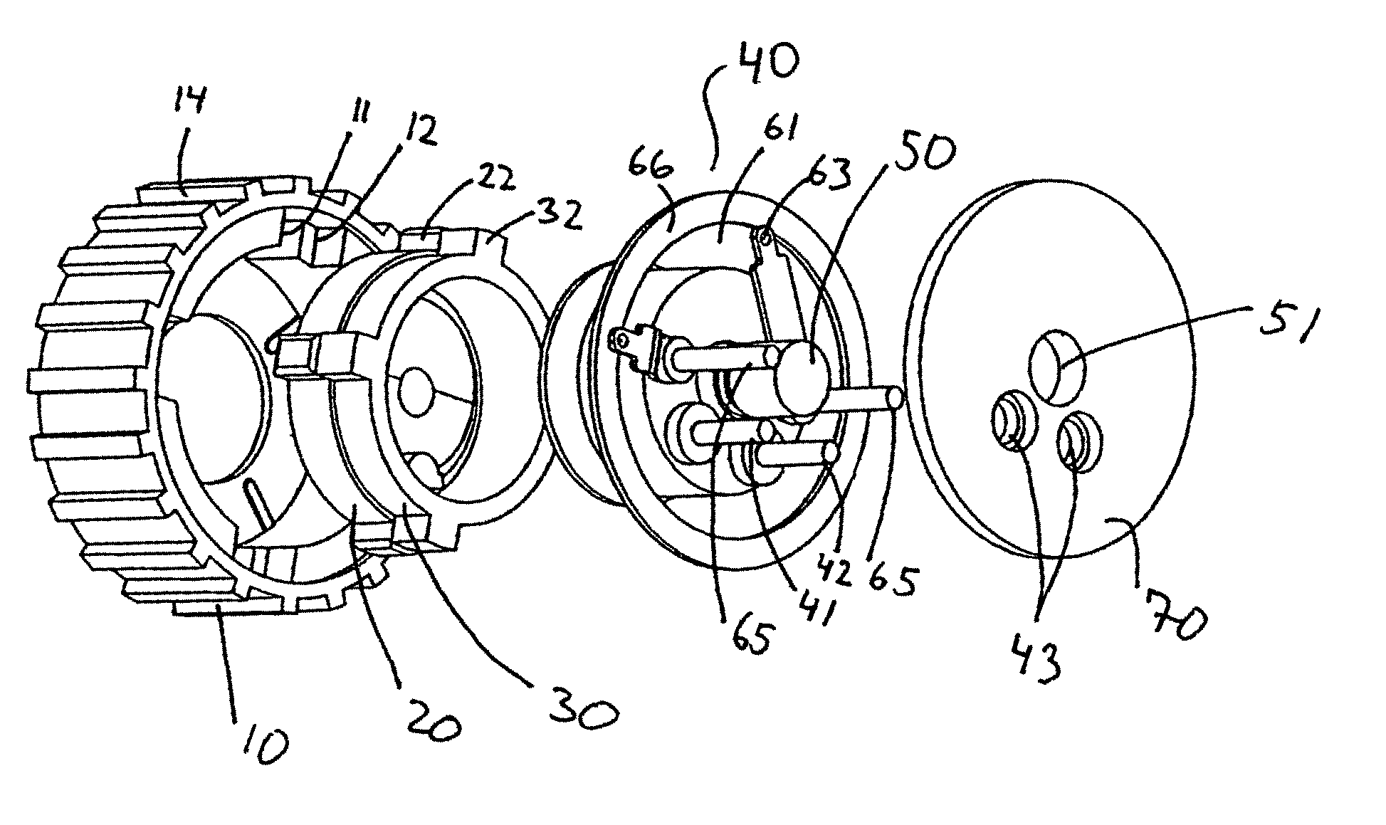
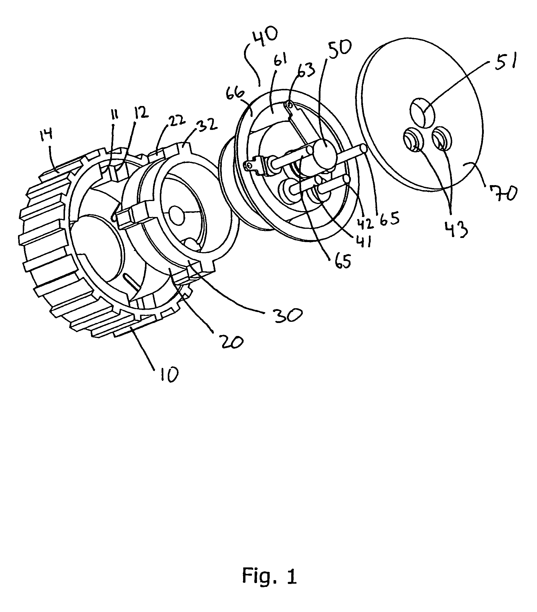
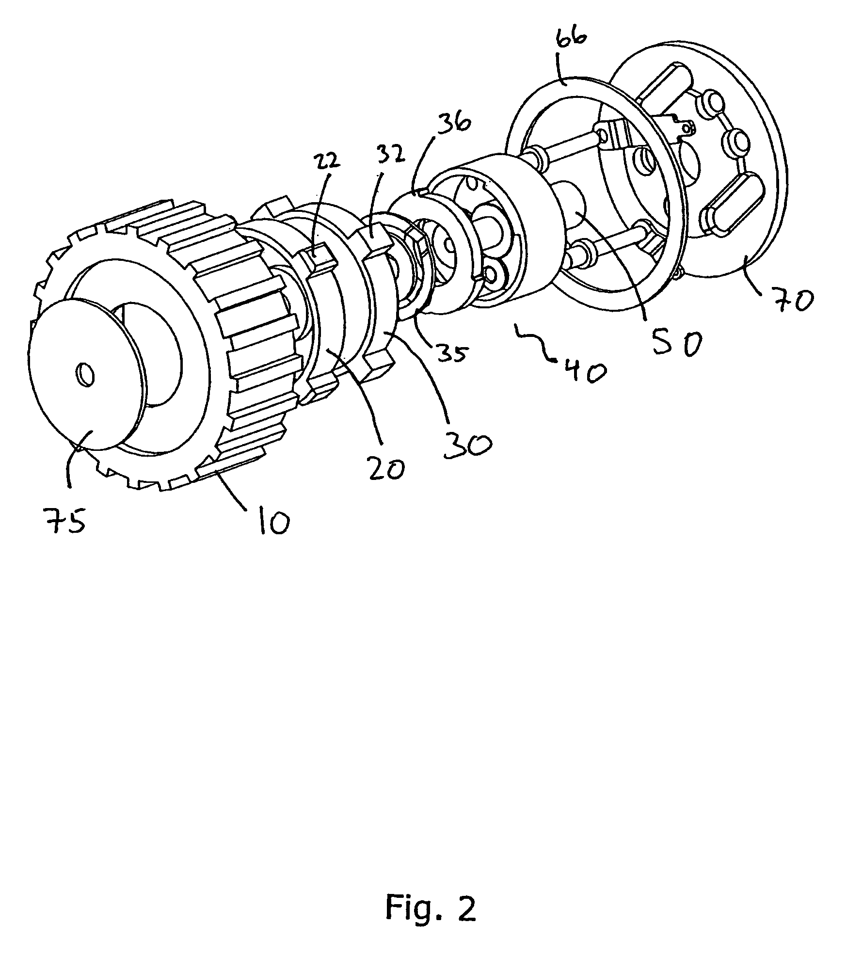
[0021]FIG. 1 shows, in an partly exploded view, a roller arrangement according to a preferred embodiment of the present invention. A wheel-like roller 10 with a hollow part serves as control knob being externally accessible to a user. The roller 10 has four recesses 11,12 equally spaced on an inner periphery of the roller, a deepness of the recesses 11 and the recesses 12 being different (not visible in FIG. 1). The recesses 12 towards an open part of the roller 10 are deeper than the recesses 11 towards a bottom part of the roller 10.

[0022]The hollow part of the roller 10 is adapted to receive a resilient member 20 being shaped as a ring. Four protrusions 22 on an outer periphery of the resilient member 20 extend in a radial direction away from a centre defined by the ring. The protrusions 22 are equally space along a periphery of the ring so as to fit tightly into the recesses 11 of the roller 10. Another ring shaped member 30 is adapted to fit tightly into the resilient member 20...


PUM


Abstract

A combined roller and push switch assembly includes a substantially hollow wheel-like roller member being displaceable from an initial position to a displaced position. The combined roller and push switch assembly further includes a member for returning the roller member from the displaced position to the initial position, the returning member is a resilient member being at least partly encircled by the roller member, and a coding member for detecting rotation of the roller member in relation to an associated frame. In particular, the combined roller and push switch assembly further including a switch for indicating when the roller member is in the displaced position, the switch being at least partly encircled by the roller member.

Description

[0001]This application claims benefit of Provisional No. 60 / 451,266 filed Mar. 4, 2003.[0002]The present invention relates to a combined roller and push switch assembly, comprising a substantially hollow wheel-like roller member being displaceable from an initial position to a displaced position. In particular, the present invention relates to a combined roller and push switch assembly further comprising switching means for indicating when the roller member is in the displaced position, the switching means being at least partly encircled by the roller member.BACKGROUND OF THE INVENTION[0003]EP 0 874 382 discloses a rotary-operation type electronic component incorporating a push switch—see e.g. FIGS. 1 and 2. A revolving contact-points board 2, which functions as movable contact-points for the rotary encoder and the push switch, is attached on a fitting substrate 1—the fitting substrate 1 constituting fixed contact-points. The revolving contact-points board 2 is provided with a round...

Claims


Application Information

Patent Timeline
IPC IPC(8): H01H25/00
CPCH01H25/008H01H2019/146H01H2300/004H04R2225/61H04R25/603
Inventor J.O SLASHED.RGENSEN, MARTIN BONDORAVNKILDE, S.O SLASHED.RENVIDEBAEK, KARSTENWAGNER, MORTEN BJ.O SLASHED.RN
Owner SONION ROSKILDE
Why Eureka
Try Eureka