Layer-coded data transmitting apparatus

a transmission apparatus and coded data technology, applied in electrical devices, two-way working systems, selective content distribution, etc., can solve problems affecting video reproduction

Inactive Publication Date: 2005-12-13
HITACHI LTD
View PDF14 Cites 32 Cited by
  • Summary
  • Abstract
  • Description
  • Claims
  • Application Information

AI Technical Summary

Benefits of technology

[0022]According to a still further aspect of the present invention, there is provided a layer-coded data transmitting apparatus for transmitting layer-coded data in a single channel, which apparatus divides into low and high frequency component data each of intra-encoded image (hereinafter referred to as “I frame”) data, prediction-encoded image (hereinafter refereed to as ...

Problems solved by technology

When packet discarding occurs due to congestion of the transmission network, disordered packet discarding ...

Method used


Image

  • Layer-coded data transmitting apparatus
  • Layer-coded data transmitting apparatus
  • Layer-coded data transmitting apparatus

Examples


Embodiment Construction

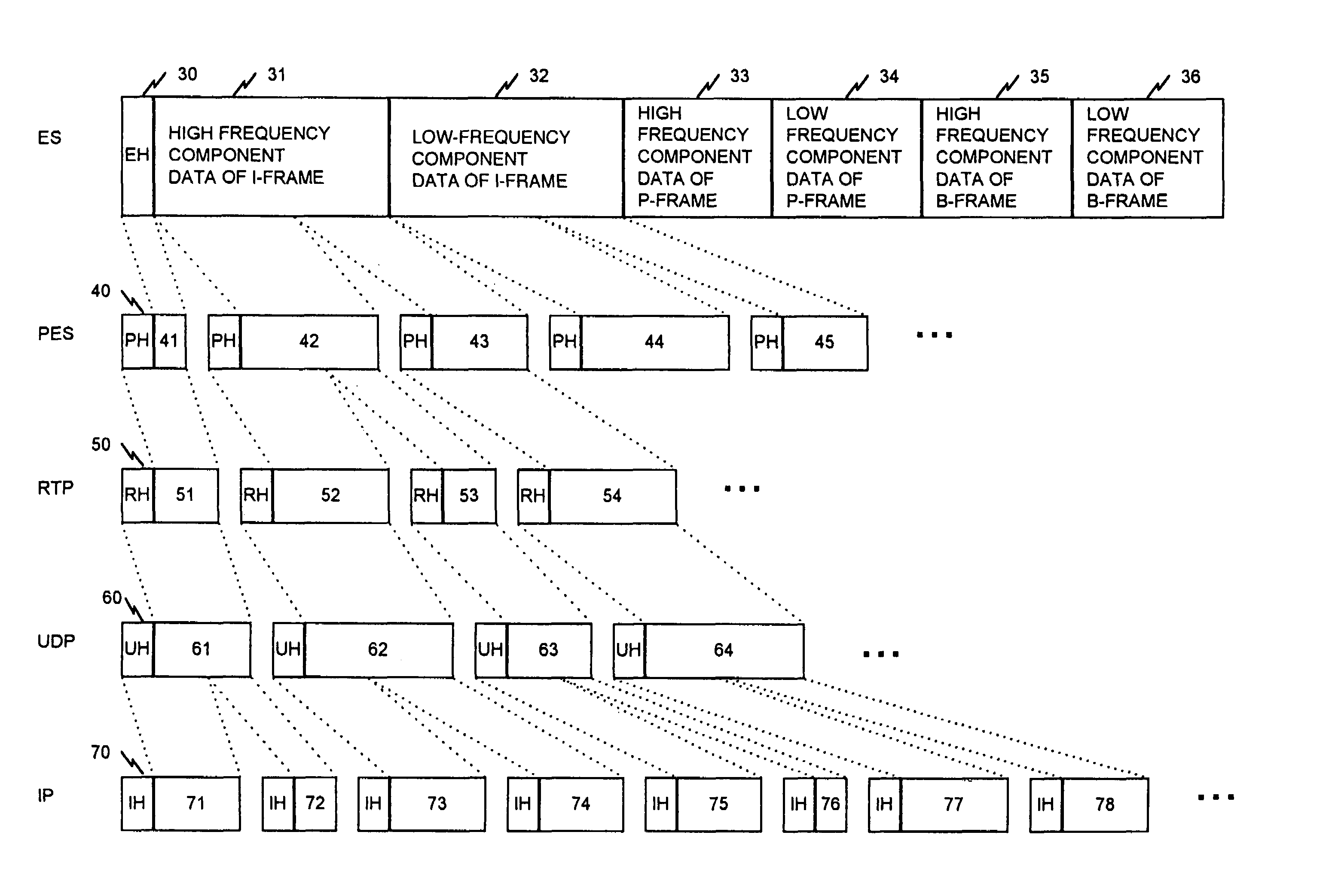
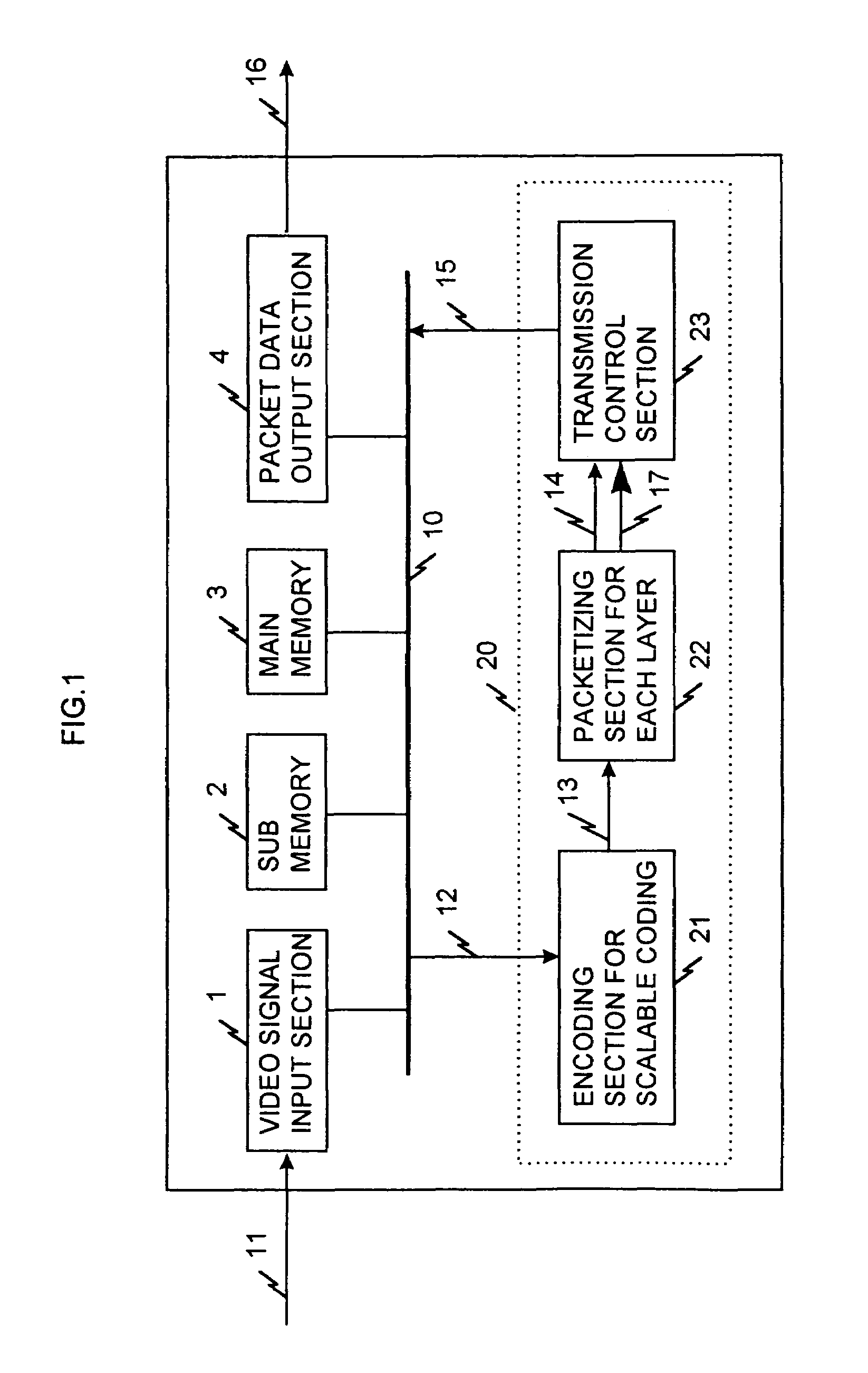
[0028]A preferred embodiment of the present invention will be described in more detail with reference to the drawings. FIG. 1 illustrates a layer-coded data transmitting apparatus according to the embodiment of the present invention. The layer-coded data transmitting apparatus includes a video signal input section 1, a central processing unit 20, a sub memory 2 which contains a processing program, a main memory 3 which temporarily stores data under operation, and a packet data output section 4 which outputs packetized layer video data, connected to a bus 10. The program stored in the sub memory 2 includes an encoding section for scalable coding 21 which layer-codes a video signal, a packtizing section 22 which packetizes layer-coded data for each layer, and a transmission control section 23 which transmits the packtized data to a network.

[0029]Then, the operation of the inventive layer-coded video data transmitting apparatus will be described next. The layer-coded data transmitting ...


PUM


Abstract

When one-video program data (layer-coded data) of a plurality of layers is transmitted in a single channel, a video signal is layer-coded in an MPEG system, the layer-coded ES (Elementary Stream) data is converted to a PES (Packetized Elementary Stream) for each layer, and the PES is then converted to a RTP (Real-Time Protocol) packet, which is then converted to a UDP (User Datagram Protocol). An identifier is then annexed to a UDP packet data for each layer to form an IP (Internet Protocol) packet.

Description

[0001]This is a continuation of application Ser. No. 09 / 389,455, filed Sep. 3, 1999.BACKGROUND OF THE INVENTION[0002]1. Field of the Invention[0003]The present invention relates to compressed coded data transmitting systems, and more particularly to an apparatus for packetizing layer-coded video data and for transmitting it.[0004]2. Description of the Related Art[0005]In the transmission of video data, a system is known which divides coded data which contains DCT (Discreet Cosine Transform) components into low and high frequency component data and packetizes them individual-ly in a H.261 encoding system which is an international standard for video conference, as described in JP-A-10-23418 laid-open on Jan. 23, 1998. In this invention, if data to be transmitted comprises low frequency components, a flag indicative of high priority is annexed to a packet for transmitting the data whereas if the data contains high frequency components, a flag indicative of low priority is annexed to th...

Claims


Application Information

Patent Timeline
IPC IPC(8): H04N7/173H04N19/00H04N19/30H04N19/423H04N19/46H04N19/503H04N19/577H04N19/593H04N19/70H04N19/80H04N19/85H04N21/2343H04N21/2389
CPCH04N21/234327H04N21/64322H04N21/6437H04N21/64792
Inventor SUZUKI, TOSHIAKIYOSHIZAWA, SATOSHIIKEZAWA, MITSURUMIMURA, ITARUKAMEYAMA, TATSUYA
Owner HITACHI LTD
Why Eureka
Try Eureka