
Method and jig for handling and transferring fusion-spliced optical fibers

a technology of optical fiber and fusion splice, which is applied in the direction of optics, instruments, optical light guides, etc., can solve the problems of inability to change or add processing devices and tools, the apparatus becomes large and very expensive for such various processes, and the loss of practically allowable splices of optical fibers

Inactive Publication Date: 2005-12-20
SUMITOMO ELECTRIC IND LTD
View PDF7 Cites 2 Cited by
  • Summary
  • Abstract
  • Description
  • Claims
  • Application Information

AI Technical Summary

Problems solved by technology

In case that a typical single-mode optical fiber and a specialty-functional optical fiber, which are different in mode-field diameter, are connected together by fusion, the resulting optical fiber cannot obtain a practically allowable splice loss without further processing its spliced portion.
However, when the fusion-spliced optical fiber requires high temperature heat treatment of its spliced portion (i.e. the TEC process), recoating and / or testing thereof, the apparatus becomes large and very expensive for such various processes since it is arranged as one apparatus.
This makes the apparatus unable to change or add processing devices and tools used thereon.
In other words, the apparatus cannot be universal in practice.

Method used


Image

  • Method and jig for handling and transferring fusion-spliced optical fibers
  • Method and jig for handling and transferring fusion-spliced optical fibers
  • Method and jig for handling and transferring fusion-spliced optical fibers

Examples


Embodiment Construction

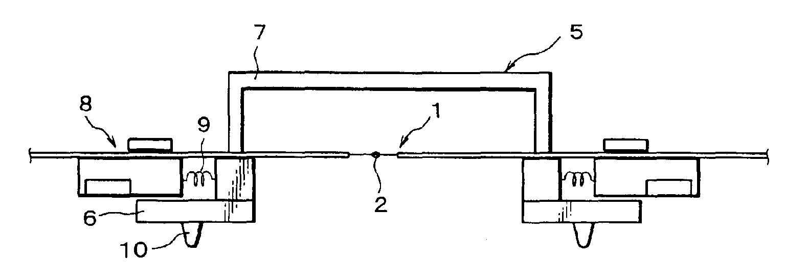
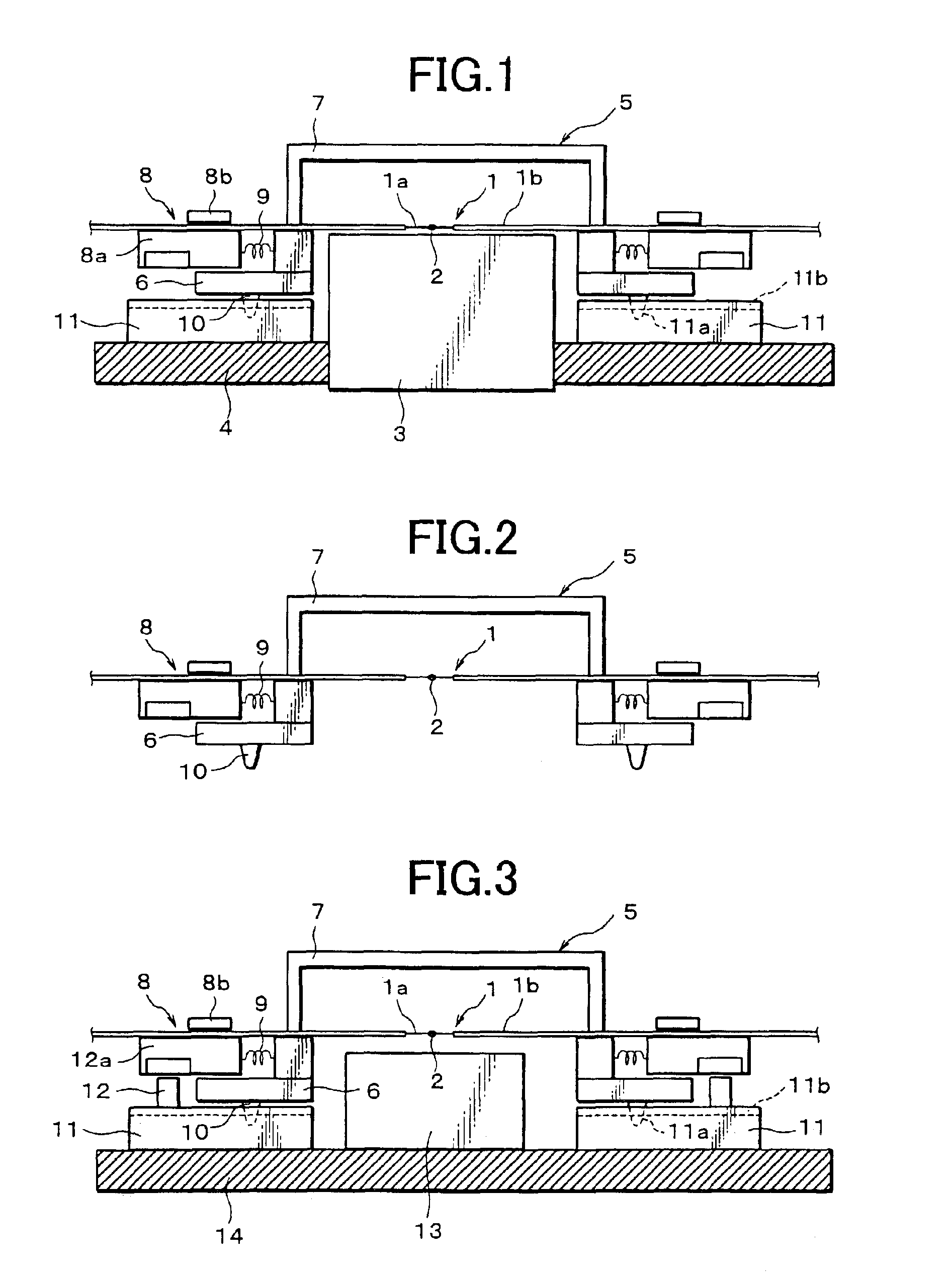
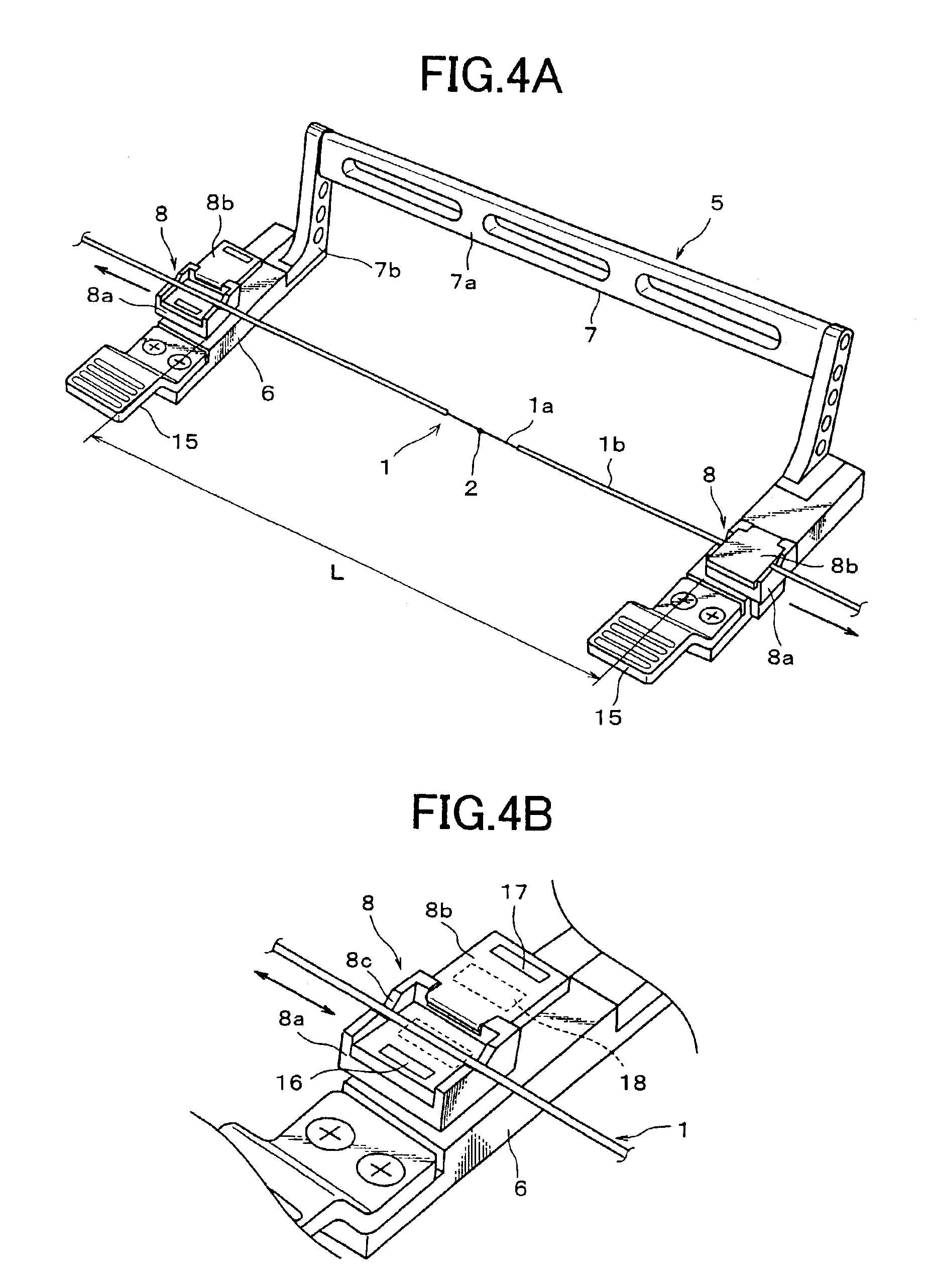
[0015]A preferred embodiment of the present invention will be described below in detail with reference to accompanying drawings. FIG. 1 illustrates an embodiment of the present invention applied at the end of a fusion-splicing process or at a later process on a different place. FIG. 2 is illustrative of an embodiment at the time of transporting a fusion-spliced optical fiber and FIG. 3 is illustrative of an embodiment at a place of a heat treatment process. In these figures, there is shown a fusion-spliced optical fiber 1, an exposed portion 1a of the optical fiber, a coated portion 1b of the fiber, a fusion-spliced portion 2, a fusion-splicer (or recoater) 3, a mounting table 4, a transferring jig 5, a clamp stand 6, a connecting arm 7, a clamp 8, clamp base 8a, a pressing plate 8b, a spring 9, a locating lug 10, a locating block 11, a magnet 12, a magnetic member 12a, a heating device 13 and a mounting table 14.

[0016]A pair of optical single fibers or multi-fiber units are butted ...


PUM


Abstract

A method for handling a fusion-spliced optical fiber and a transferring jig for transporting the optical fiber are provided. The jig is capable of holding the fusion-spliced optical fiber in a state in which a given tension is applied at the spliced portion, and stopping the application of such tension if needed. The jig is easy to transport and set to each of separate processing processes. In the method, a fusion-spliced optical fiber is clamped at coated portions thereof on both sides of the fusion-spliced portion by a pair of clamps of the jig and transported by the jig holding the optical fiber in a state wherein a given tension is applied thereto through the clamps.

Description

BACKGROUND OF THE INVENTION[0001]The present invention relates to a handling method and a jig for transferring a fusion-spliced optical fiber from a fusion splicing process to one of processes such as thermal treatment or reinforcing treatment of the spliced portion of the optical fiber.[0002]After the fusion-splicing of a pair of single-fibers or a pair of multi-fiber units, the exposed spliced portion of the optical fiber is generally reinforced by recoating with UV-cured resin or covering with a heat-shrinkable tube. In case that a typical single-mode optical fiber and a specialty-functional optical fiber, which are different in mode-field diameter, are connected together by fusion, the resulting optical fiber cannot obtain a practically allowable splice loss without further processing its spliced portion. Therefore, in one of known methods, the spliced portion and neighboring portion thereof are further processed by heating to form a smoothly expanded taper core diameter such th...

Claims


Application Information

Patent Timeline
IPC IPC(8): G02B6/255G02B6/38
CPCG02B6/2551G02B6/2552G02B6/2555
Inventor KOIKE, REIHATTORI, KAZUNARIMORIYA, TOMOMI
Owner SUMITOMO ELECTRIC IND LTD
Learn More