Dual discharge trigger sprayer

a trigger sprayer and dual-discharge technology, applied in the direction of packaging, liquid transfer devices, single-unit apparatuses, etc., can solve problems such as confusion among users

Active Publication Date: 2005-12-27
SILGAN DISPENSING SYST CORP
View PDF16 Cites 58 Cited by
  • Summary
  • Abstract
  • Description
  • Claims
  • Application Information

AI Technical Summary

Problems solved by technology

If the disparate fluids are mixed prior to discharge through a single orifice, the user may be confused, believing that only the single fluid is being sprayed.

Method used


Image

  • Dual discharge trigger sprayer
  • Dual discharge trigger sprayer
  • Dual discharge trigger sprayer

Examples


Embodiment Construction

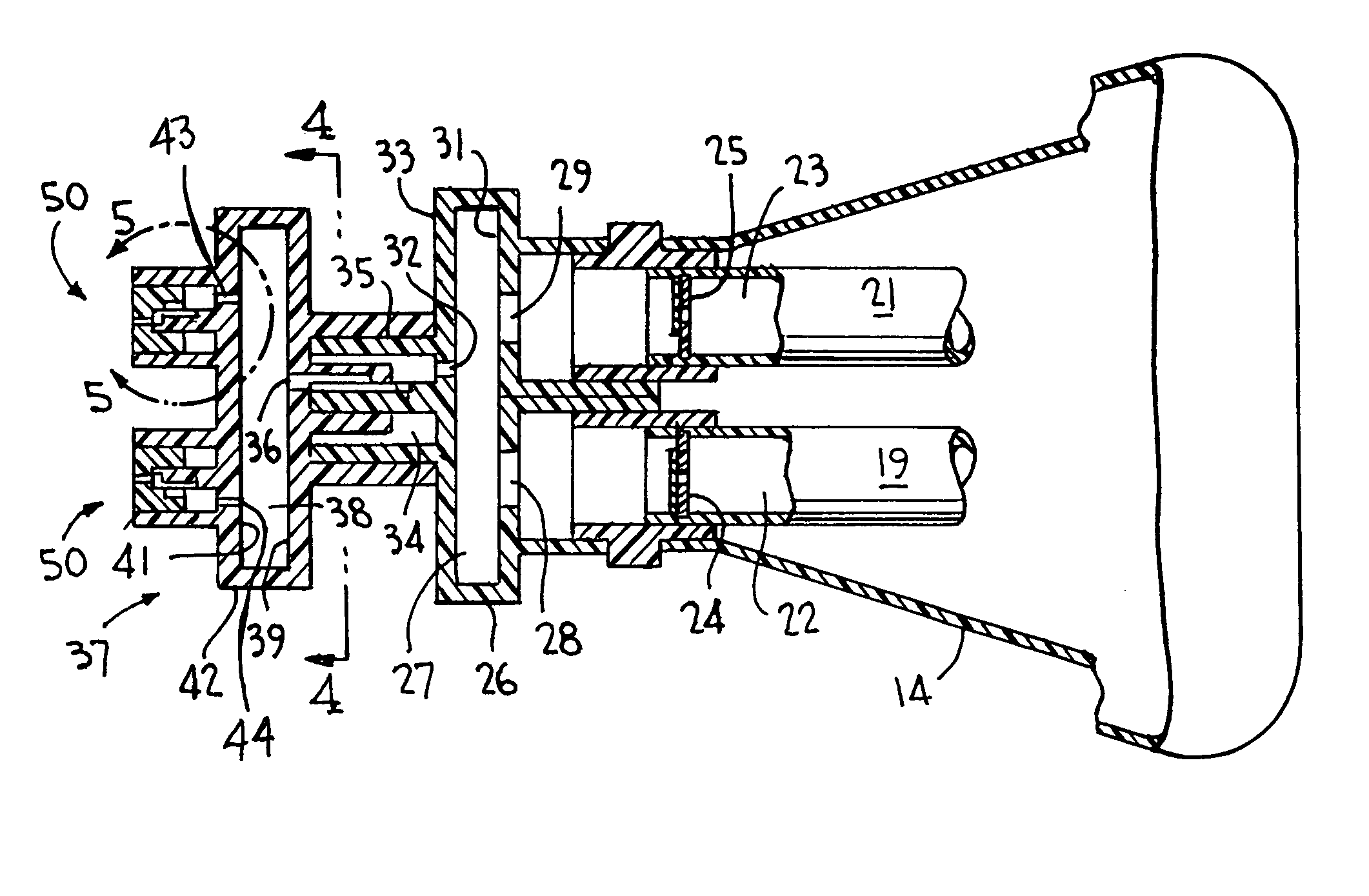
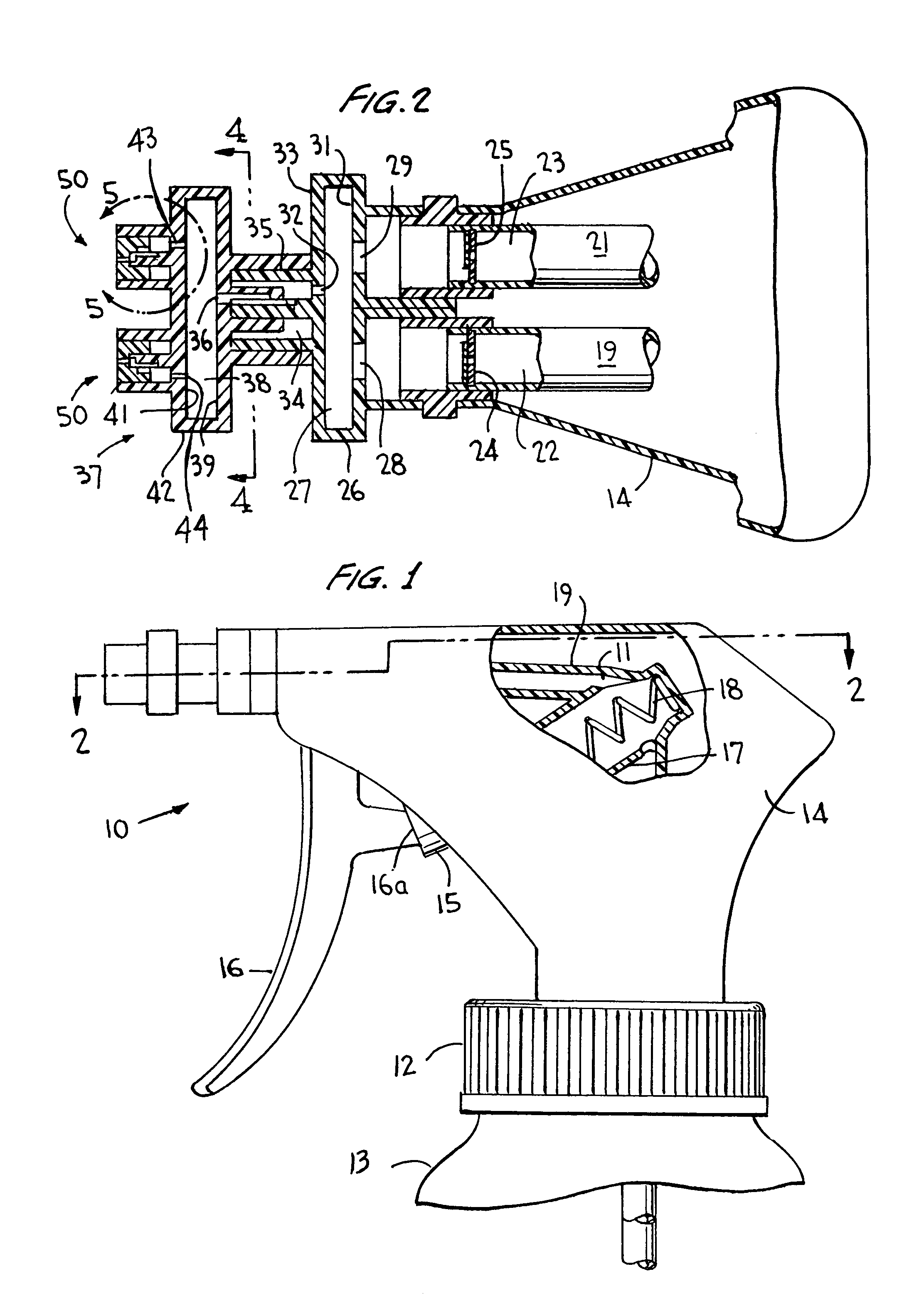
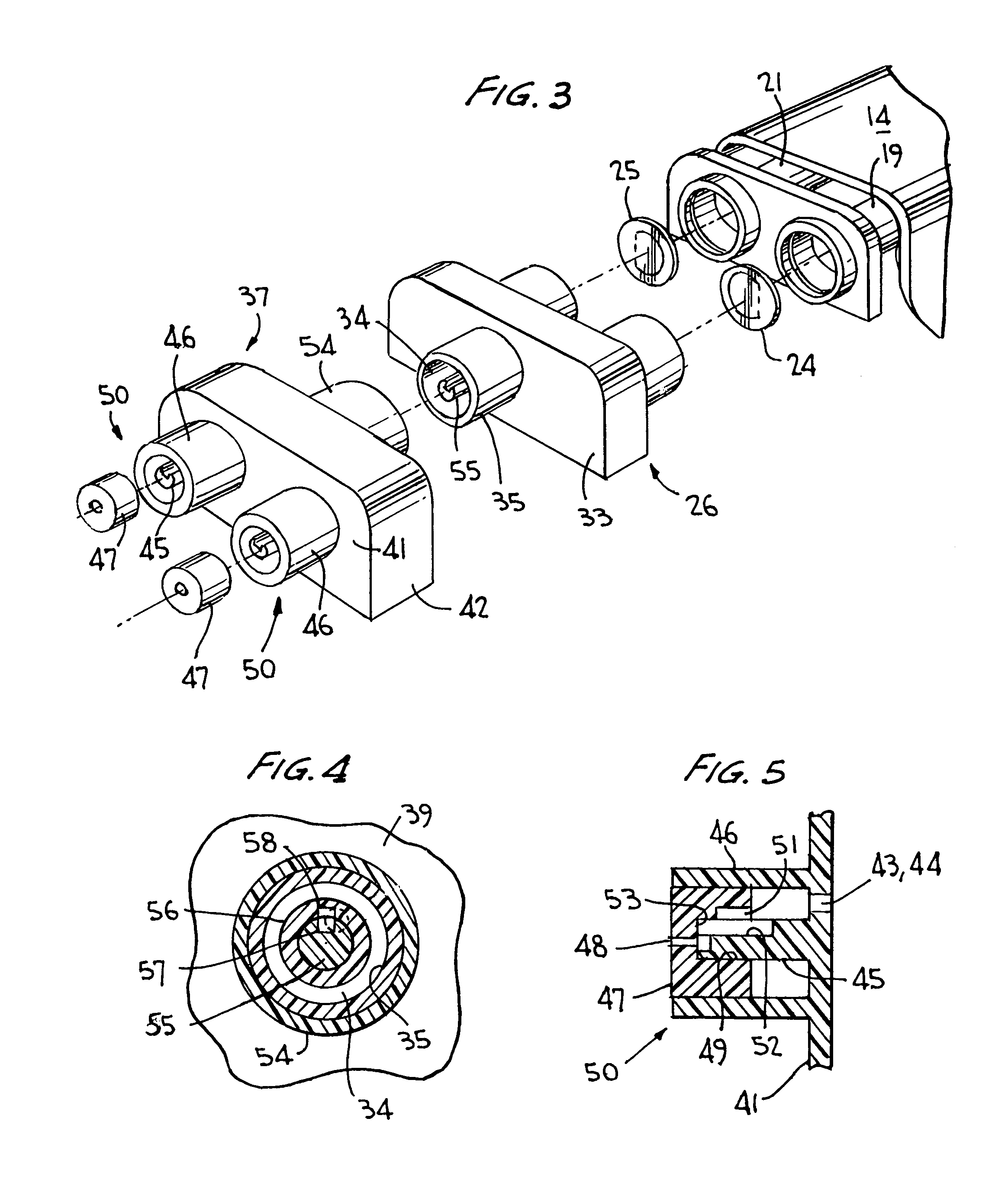
[0011]Turning now to the drawings wherein like reference characters refer to like and corresponding parts throughout the several views, the dual trigger sprayer incorporating the invention is generally designated 10 in FIG. 1 as including a pump body 11 supporting a container closure 12 for mounting the dispenser to a dual compartmented container 13 of the type disclosed, for example, in U.S. Pat. No. 5,535,950, the entirety of the disclosure of which being specifically incorporated herein by reference. The pump body is covered by a shroud 14 and contains a pair of side-by-side pump pistons 15 (only one shown) operating in a pair of side-by-side pump cylinders 17 to define therewith variable volume pump chambers in known manner. A trigger actuator in the form of a single trigger lever 16 is hingedly mounted to the pump body in engagement with the pistons as at 16a for simultaneously reciprocating the pistons in their bores against the force of suitable return springs 18 (only one sh...


PUM


Abstract

A trigger actuated fluid dispenser for simultaneously dispensing disparate fluids separately stored in separate fluid compartments of a container includes a mixing manifold for intimately mixing the fluids together and the nozzle assembly in which the mixture is channeled into a pair of spray nozzles through which the mixture of fluids issue as it sprays, upon simultaneous pumping of the disparate fluids by a single trigger actuator directing the disparate fluids along separate discharge paths to the mixing manifold.

Description

BACKGROUND OF THE INVENTION[0001]This invention relates generally to a dual discharge sprayer for simultaneously discharging different fluids separately stored in different fluid compartments, and more particularly to such a dispenser for simultaneously discharging a mixture of the different fluids through separate discharge spray nozzles.[0002]U.S. Pat. No. 6,550,694 discloses a dual trigger sprayer which mixes different fluids in a common discharge passage prior to their being dispensed from the discharge passage as a spray through a single discharge opening. U.S. Pat. No. 5,535,950 likewise discloses a dual trigger sprayer for simultaneously discharging separately stored disparate fluids as a mixture prior to dispensing through a single spray discharge orifice. This patent further discloses a dual trigger sprayer for simultaneously dispensing disparate fluids separately stored through discharge passages and through a pair of separate spray discharge orifices for mixing together a...

Claims


Application Information

Patent Timeline
Patent Type & Authority Patents(United States)
IPC IPC(8): B05B11/00
CPCB05B11/3084B05B11/3011B05B11/1011B05B11/1084
Inventor SWEETON, STEVE L.
Owner SILGAN DISPENSING SYST CORP
Why Eureka
Try Eureka