Indicator circuit arrangement of a transmission cable for computer

a technology of indicator circuit and transmission cable, which is applied in the direction of electrical equipment, incorrect coupling prevention, coupling device connection, etc., can solve the problems of still not satisfactory use, user cannot quickly inspect the connection status of one specific transmission cable from a group of transmission cables, etc., and achieve the effect of quick identification

Inactive Publication Date: 2005-12-27
CHEN WILSON
View PDF5 Cites 54 Cited by
  • Summary
  • Abstract
  • Description
  • Claims
  • Application Information

AI Technical Summary

Problems solved by technology

This design of transmission cable is functional, however it is still not satisfactory in use.
Further, when several transmission cables are arranged together, the user cannot quickly inspect the connection status of one specific transmission cable from a group of transmission cables.

Method used


Image

  • Indicator circuit arrangement of a transmission cable for computer
  • Indicator circuit arrangement of a transmission cable for computer
  • Indicator circuit arrangement of a transmission cable for computer

Examples


Embodiment Construction

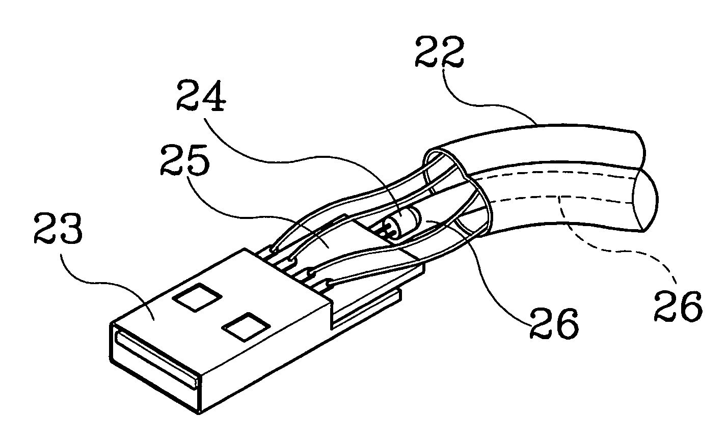
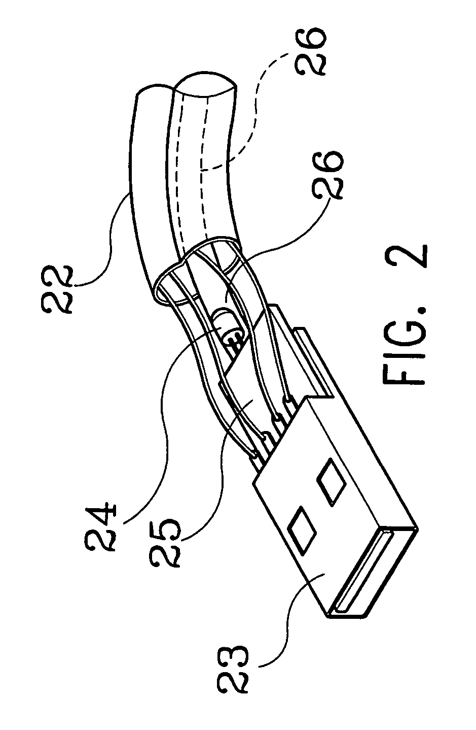
[0011]Referring to FIGS. 2˜5, a transmission cable 20 is shown for connecting a peripheral apparatus to a computer. The transmission cable 20 can be a universal serial bus or IEEE1394 parallel bus design, comprising a cable 22, two electric connectors 21, 21′ respectively connected to the two distal ends of the cable 22, a cord-like electroluminescent lamp 26 axially mounted in the cable 22 and electrically connected between the electric connectors 21, 21′. The cable 22 has an electrically insulative transparent outer shell. The electric connectors 21, 21′ each have an indicator light (lighting emitting diode) 24 installed therein. Further, a detector converter circuit 25 is installed in the housing 23 or 23′ of one electric connector 21 or 21′.

[0012]The detector converter circuit 25 is adapted to detect normal connection of the transmission cable between the computer and the peripheral apparatus and to convert DC to AC, i.e., to convert 5V obtained from the computer into the desire...


PUM


Abstract

An indicator circuit arrangement of a transmission cable for connecting a peripheral apparatus to a computer is disclosed to have a cord-like electroluminescent lamp axially extended in the cable between the electric connectors at the ends of the cable, and a detector and converter circuit installed in one electric connector and adapted to detect the connection status of the cable between the computer and the peripheral apparatus and to drive on the cord-like electroluminescent lamp upon normal connection of the cable between the computer and the peripheral apparatus.

Description

BACKGROUND OF THE INVENTION[0001]1. Field of the Invention[0002]The present invention relates to a transmission cable for computer and more particularly, to the indicator circuit arrangement of a transmission cable for computer, which uses a detector converter circuit to detect the connection status of the cable and to drive on a cord-like electroluminescent lamp in the cable.[0003]2. Description of the Related Art[0004]FIG. 1 illustrates a transmission cable for computer according to the prior art. According to this design, the transmission cable 10 comprises a cable 12 and two electric connectors 11, 11′ at the ends of the cable 12. The transmission cable 10 can be a USB (universal serial bus) design or IEEE1394 parallel bus design. The electric connectors 11, 11′ each have a LED (light emitting diode) mounted on the inside. One electric connector 11 or 11′ has a detecting circuit (not shown) provided on the inside. The detecting circuit detects connection and signal transmission ...

Claims


Application Information

Patent Timeline
Patent Type & Authority Patents(United States)
IPC IPC(8): H01R3/00H01R11/00H01R13/641H01R13/66H01R13/717
CPCH01R13/641H01R13/6641H01R13/717H01R13/7172H01R13/7175H01R31/065
Inventor CHEN, WILSON
Owner CHEN WILSON
Why Eureka
Try Eureka