Ratchet wheel mounting structure for wrench

a technology of ratchet wheels and mounting structures, which is applied in the field of wrenches, can solve the problems of low torque values, insufficient transfer of output force, and rapid wear of the ratchet wheels, and achieve the effect of eliminating the drawbacks

Inactive Publication Date: 2006-01-03
HSIEN CHIH CHING
View PDF2 Cites 2 Cited by
  • Summary
  • Abstract
  • Description
  • Claims
  • Application Information

AI Technical Summary

Benefits of technology

[0004]The present invention has been accomplished to provide a rat...

Problems solved by technology

The teeth of these ratchet wheels wear quickly as used for a longer time and have low torque values.
Further, when the prior art wrench is engaged with the toothed stop block in the box of the wrench, but, in this prior art, output force is not fully transferred from the wrench to the ratchet wheel and then to a workpiece. FIG. 3 shows still another design of ratchet wheel according to the prior art.
When the wrench is twisted to rotate a workpiece, the teeth of the ratchet wheel may break easily, and the friction between the ends of each teeth of the ratchet wheel and the inside wall of the box of the wrench affects the performance of the wrench.
An...

Method used


Image

  • Ratchet wheel mounting structure for wrench
  • Ratchet wheel mounting structure for wrench
  • Ratchet wheel mounting structure for wrench

Examples


Embodiment Construction

[0019]Referring to FIGS. 4, 5 and 13, a ratchet wheel 20 and a stop block 30 are mounted in the box 11 of a wrench body 10. The stop block 30 is a toothed member engaged with the ratchet wheel 20 and adapted to control the direction of rotation of the ratchet wheel 20.

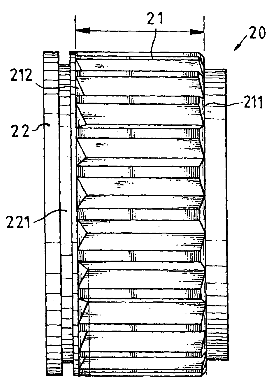
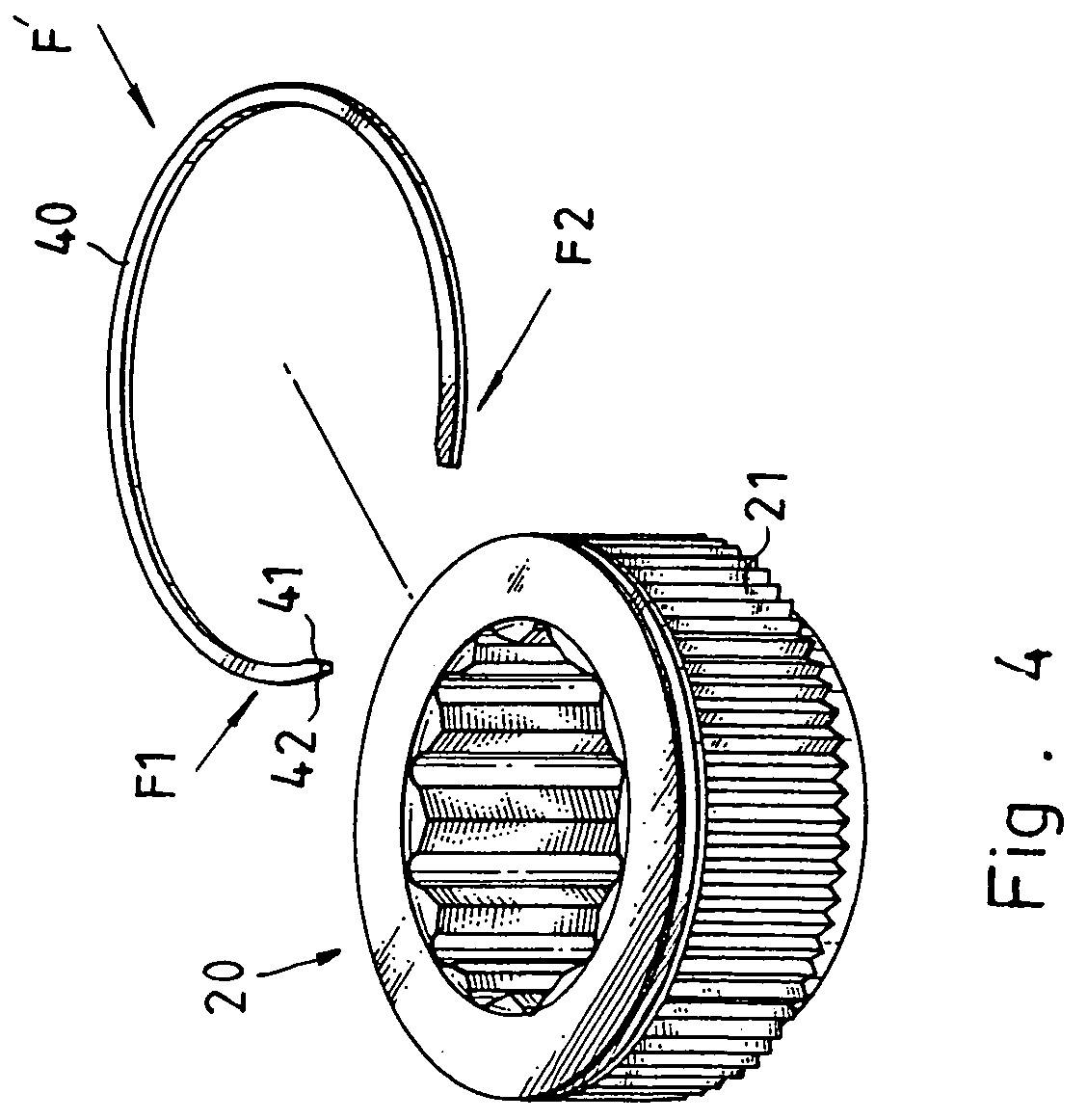
[0020]The ratchet wheel 20 has teeth 21 arranged around the periphery thereof, a locating block 22 at one side thereof, and a locating groove 221 extended around the locating block 22 for the positioning of a retainer ring 40, which secures the ratchet wheel 20 to the inside of the box 11 of the wrench body 10. The outer diameter of the locating block 22 is equal to the outer diameter around the teeth 21.

[0021]Referring to FIG. 6, each tooth 21 has a chamfered end 211 at one end thereof. Further, a reinforcing bevel end 212 is provided in the valley between another ends of each two adjacent teeth 21 adjacent to the locating block 22. The structure will reinforce the structural strength of the teeth for smooth rotation....


PUM


Abstract

A ratchet wheel mounting structure comprises a ratchet wheel mounted in a box of a wrench body and meshed with a toothed stop block in said box, and a retainer ring mounted in between said box and said ratchet wheel to secure said ratchet wheel to said box, said ratchet wheel having teeth arranged around the periphery thereof, a locating block at one side of the ratchet wheel, and a locating groove being formed around the periphery of said locating block for positioning said retainer ring. Each tooth of said ratchet wheel is chamfered at one end thereof far away from the locating block; and a reinforcing bevel is provided in the valley between roots of another ends of each two adjacent teeth of said ratchet wheel adjacent to said locating block. Or each tooth is chamfered at two ends and thus no bevel slop is formed.

Description

[0001]The present invention is a continuation in part (CIP) of U.S. patent Ser. No. 10 / 213,301, now abandoned, filed Aug. 7, 2002, assigned to the inventor of the present invention, thereby, the content of U.S. patent Ser. No. 10 / 213,301 is incorporated into the present invention as a part of the present invention.FIELD OF THE INVENTION[0002]The present invention relates to wrenches, and more specifically, to a ratchet wheel mounting structure for wrench, which achieves high performance.BACKGROUND OF THE INVENTION[0003]FIGS. 1 and 2 show two different ratchet wheel designs according to the prior art. These ratchet wheels are made through latching and milling processes, having R-angle or straight teeth. The teeth of these ratchet wheels wear quickly as used for a longer time and have low torque values. Further, when the prior art wrench is engaged with the toothed stop block in the box of the wrench, but, in this prior art, output force is not fully transferred from the wrench to the...

Claims


Application Information

Patent Timeline
IPC IPC(8): B25B13/46
CPCB25B13/463
Inventor HSIEN, CHIH-CHING
Owner HSIEN CHIH CHING
Why Eureka
Try Eureka