Boat propulsion system

a propulsion system and boat technology, applied in the direction of motor-driven power plants, vessel parts, gearing, etc., can solve the problems that the boat equipped with the conventional propulsion system in stationary cannot be smoothly accelerated to get the desired high speed, and the above-conventional boat propulsion system has a problem, so as to achieve smooth acceleration of the prime mover and lighten the resistance to the prime mover

Inactive Publication Date: 2006-01-24
KANZAKI KOKYUKOKI MFG
View PDF12 Cites 7 Cited by
  • Summary
  • Abstract
  • Description
  • Claims
  • Application Information

AI Technical Summary

Benefits of technology

[0007]An object of the invention is to provide a boat propulsion system interposed between a prime mover and a propeller shaft, wherein resistance to the prime mover is lightened to smoothen acceleration of the prime mover.
[0010]Preferably, the gear transmission part includes a planetary gear which combines the input rotary force of the hydraulic pump and the output rotary force of the hydraulic motor, and transmits the resultant rotary force to the propeller shaft. Such a simple and compact planetary gear can transmit the assistant force of the hydraulic motor to the gear transmission part.
[0011]Preferably, the swash plate of the hydraulic pump being movable into one of first and second opposite ranges from a neutral position, and the gear transmission part having a proper deceleration ratio established by stopping the hydraulic motor, wherein, if the output rotary speed of the prime mover is lower than a predetermined speed, the swash plate of the hydraulic pump is disposed in the first range to rotate the hydraulic motor so that a deceleration ratio of the hydro-mechanical transmission becomes larger than the proper deceleration ratio of the gear transmission part. Therefore, the acceleration of the prime mover from its idling speed to the predetermined speed is smoothened.
[0012]Further preferably, the swash plate of the hydraulic pump in the first range is moved to reduce the displacement of the hydraulic pump as the output rotary speed of the prime mover is increased. Therefore, the increased deceleration ratio of the hydro-mechanical transmission is appropriately reduced as far as the prime mover is accelerated.
[0018]Preferably, the swash plate of the hydraulic pump is movable into one of first and second opposite ranges from a neutral position. The swash plate of the hydraulic pump is set in the first range to rotate the propeller shaft for forward propelling, and set in the second range to rotate the propeller shaft for backward propelling. Therefore, the boat propulsion system requiring no reverser for selecting the propelling direction of the boat can be compacted and reduced in costs.
[0019]Preferably, the hydraulic motor includes a movable swash plate which is moved to reduce the displacement of the hydraulic motor when the swash plate of the hydraulic pump reaches a limit position of either the first or second range away from the neutral position.

Problems solved by technology

However, the above conventional boat propulsion system has a problem.
This is the reason why the boat equipped with the conventional propulsion system in stationary cannot be smoothly accelerated to get a desired high speed.

Method used


Image

  • Boat propulsion system
  • Boat propulsion system
  • Boat propulsion system

Examples


first embodiment

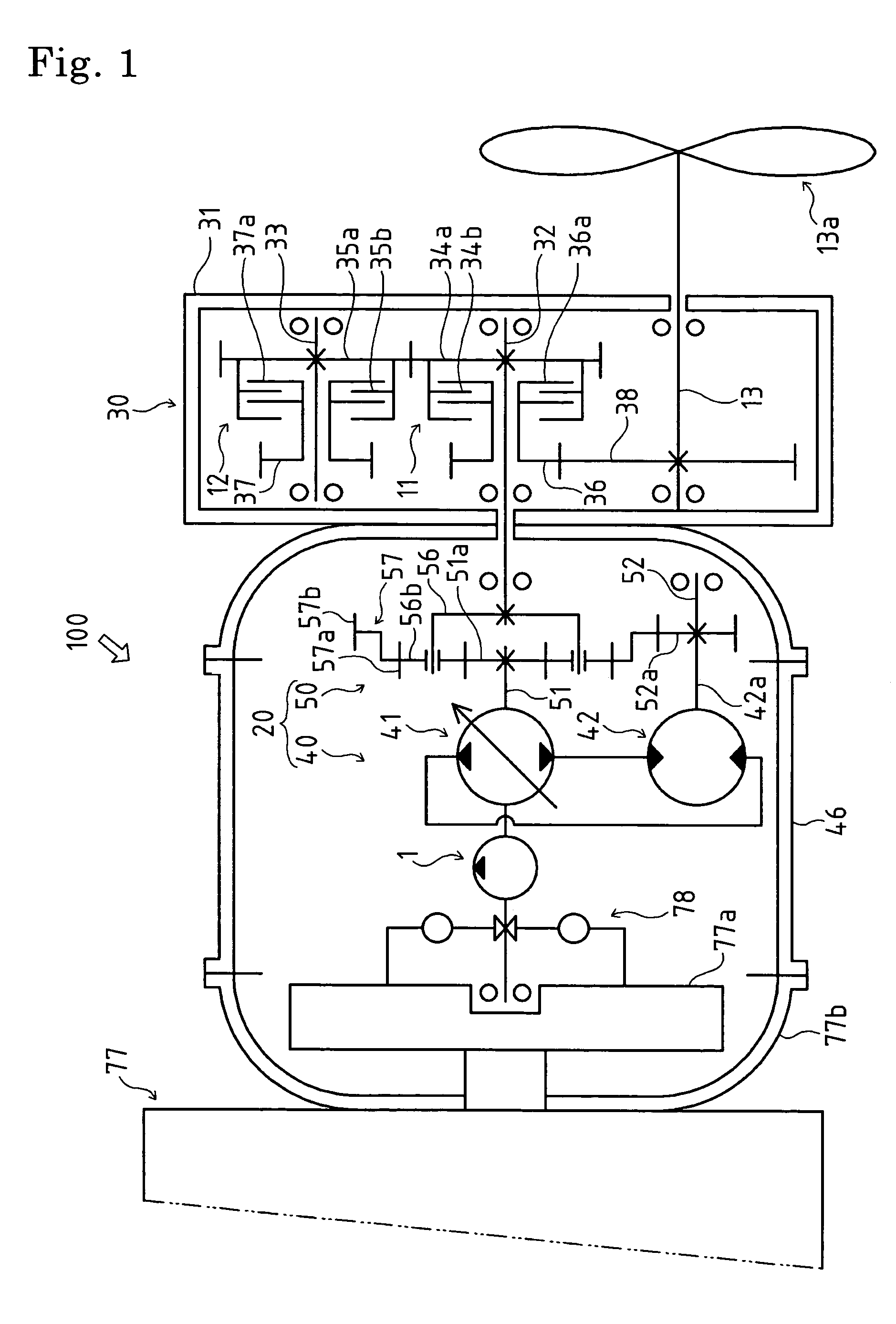
[0030]Boat propulsion system 100, according to the invention, comprises a hydro-mechanical transmission (HMT) 20 including a hydrostatic transmission part (HST) part 40 and a gear transmission part 50. HST part 40 includes a hydraulic pump 41 driven by engine 77, and a hydraulic motor 42 fluidly connected to hydraulic pump 41. HMT 20 is constructed as an output-dividing type, wherein gear transmission part 50 is driven by engine 77 (by the input rotary force of HST part 40) with the assistance of hydraulic motor 42 (of the output rotary force of HST part 40). Gear transmission part 50 includes a later-discussed planetary gear (gears) which combine the input rotary force of hydraulic pump 41 (the output rotary force of engine 77) and the output rotary force of hydraulic motor 42 so as to transmit the resultant force to hydraulic clutch system 30.

[0031]Hydraulic clutch system 30 includes a hydraulic forward propelling clutch 11 and a hydraulic backward propelling clutch 12. Either clu...

second embodiment

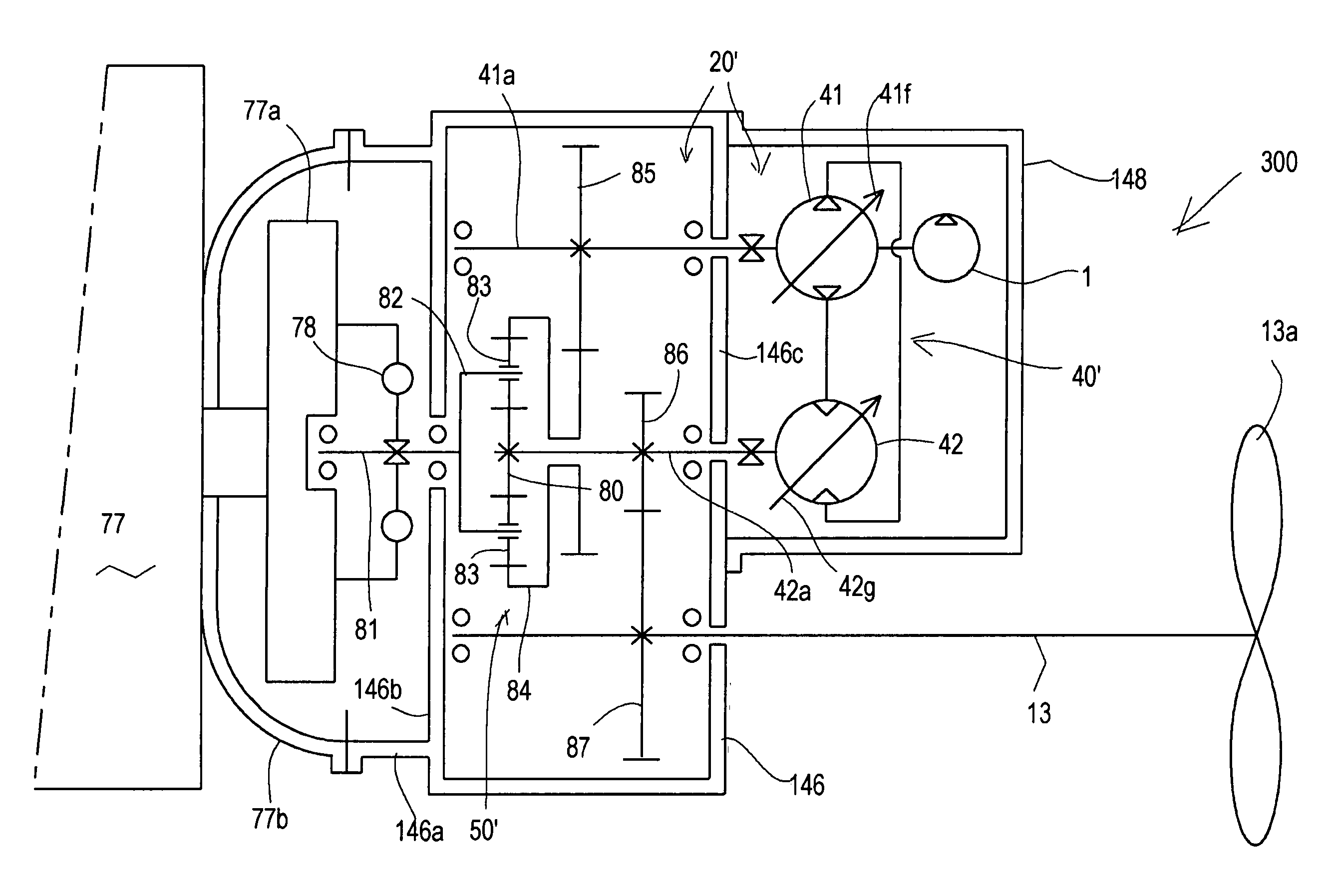
[0078]A boat propulsion system 300 shown in FIG. 6 according to the invention will be described. Boat propulsion system 300 interposed between engine 77 and propeller shaft 13 includes a gear transmission casing 146 and an HST casing 148. Gear transmission casing 146 has a rear end wall 146c from which propeller shaft 13 projects rearward. HST casing 148 is attached at its front end to rear end wall 146c of gear transmission casing 146, so as to be overhung rearward from gear transmission casing 146 above the portion of propeller shaft 13 projecting rearward from gear transmission casing 146. Alternatively, HST casing 148 may be replaced with a part of gear transmission casing 146.

[0079]Gear transmission casing 146 has a front wall 146b from which a forwardly open front portion 146a projects forward to be connected to the rear open end of flywheel housing 77b so as to enclose flywheel 77a of engine 77. In gear transmission casing 146, propeller shaft 13 is journalled at a front end ...


PUM


Abstract

A boat propulsion system interposed between a prime mover and a propeller shaft comprises a hydro-mechanical transmission including a hydrostatic transmission part and a gear transmission part. The hydrostatic transmission part includes a variable displacement hydraulic pump having a movable swash plate and a hydraulic motor fluidly connected to the hydraulic pump. The hydraulic pump is driven by the output rotary force of the prime mover. The gear transmission part is drivingly interposed between the hydrostatic transmission part and the propeller shaft so that the gear transmission part is driven by the input rotary force of the hydraulic pump with the assistance of the output rotary force of the hydraulic motor. A hydraulic clutch system may be interposed between the gear transmission part of the hydro-mechanical transmission and the propeller shaft so as to select one of opposite output rotary directions of the propeller shaft.

Description

BACKGROUND OF THE INVENTION[0001]1. Field of the Invention[0002]The invention relates to a boat propulsion improved in acceleration.[0003]2. Related Art[0004]As disclosed in the Japanese Laid Open Gazette No. Hei 10-194196, there is a well-known conventional boat propulsion system having a pair of hydraulic clutches for forward propelling and backward propelling on its drive train between an engine and a propeller shaft.[0005]The conventional system as disclosed in the document includes first, second and third shafts. The first shaft is coupled to a flywheel of the engine. The second shaft is disposed in parallel to the first shaft and drivingly connected to the first shaft through meshing gears fixed on the respective shafts so as to rotate opposite to the first shaft. The meshing gears between the first and second shafts do not serve as a deceleration gear, i.e., the gear ratio therebetween is 1:1. The third shaft serves as the propeller shaft. Each of the first and second shafts ...

Claims


Application Information

Patent Timeline
Patent Type & Authority Patents(United States)
IPC IPC(8): B63H23/00B63H23/08B63H23/26B63H23/30F16H47/04
CPCB63H23/26F16H47/04F16H2037/088B63H23/08B63H2023/305
Inventor OHTSUKI, KAZUHIKO
Owner KANZAKI KOKYUKOKI MFG
Why Eureka
Try Eureka