Sensor and guide wire assembly

a technology of guide wire and sensor, which is applied in the direction of sensors, catheters, diagnostics, etc., can solve the problems of so-called bending artefacts, and achieve the effect of cheaper manufacturing, same or better characteristics regarding resistance to bending artefacts

Inactive Publication Date: 2006-02-07
ST JUDE MEDICAL COORDINATION CENT
View PDF9 Cites 55 Cited by
  • Summary
  • Abstract
  • Description
  • Claims
  • Application Information

AI Technical Summary

Benefits of technology

[0008]An object of the present invention is to provide a new and improved design for a sensor chip so that, when the sensor chip is mounted in a sensor and guide wire assembly, the sensor and guide wire assembly will have the same or better characteristics regarding resistance against bending artefacts. Preferably, the sensor and guide wire assembly should at the same time be easier and thereby cheaper to manufacture.

Problems solved by technology

As is recognized in U.S. Pat. Nos. 6,112,598 and 6,167,763, which also are assigned to the present assignee, a potential problem with this kind of guide wire mounted sensors is the occurrence of so-called bending artefacts.

Method used


Image

  • Sensor and guide wire assembly
  • Sensor and guide wire assembly
  • Sensor and guide wire assembly

Examples


Embodiment Construction

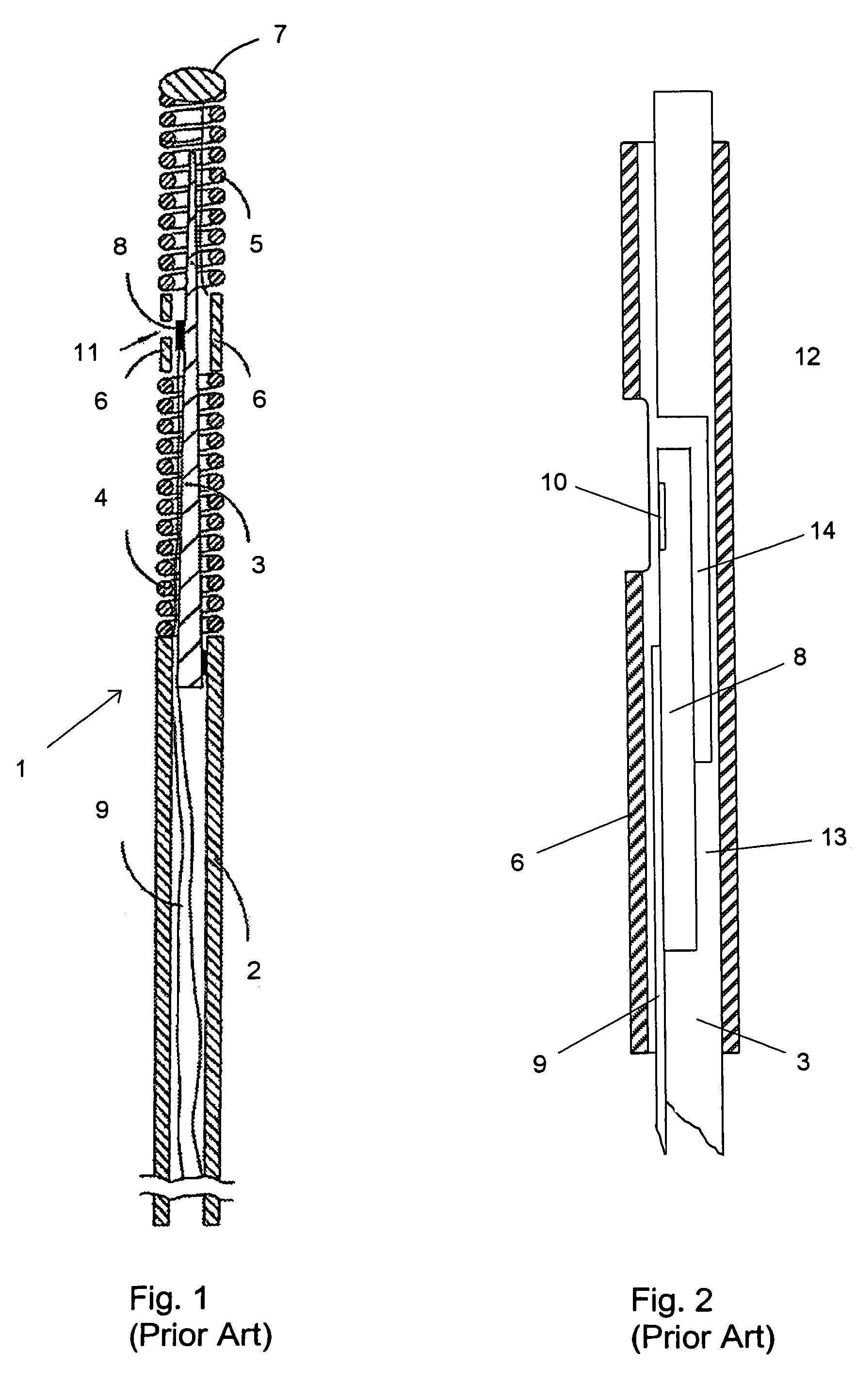
[0022]For better understanding of the context in which a sensor chip according to the present invention is going to be used, a sensor and guide wire assembly 1 of a conventional design is illustrated in FIG. 1. The sensor guide 1 comprises a hollow tube 2, a core wire 3, a first coil 4, a second coil 5, a jacket or sleeve 6, a dome-shaped tip 7, a sensor element or chip 8, and one or several electrical leads 9. The proximal end of the first coil 4 is attached to the distal end of the hollow tube 2, while the distal end of the first coil 4 is attached to the proximal end of the jacket 6. The proximal end of the second coil 5 is connected to the distal end of the jacket 6, and the dome-shaped tip 7 is attached to the distal end of the second coil 5. The core wire 3 is at least partly disposed inside the hollow tube 2 such that the distal portion of the core wire 3 extends out of the hollow tube 2 and into the second coil 5. The sensor element 8 is mounted on the core wire 3 at the pos...


PUM

PropertyMeasurementUnit
shapeaaaaaaaaaa
flexibleaaaaaaaaaa
pressureaaaaaaaaaa

Abstract

A sensor and guide wire assembly (21; 31; 41) for intravascular measurements of physiological variables in a living body includes a core wire (22; 32; 42) and sensor element (23; 33; 43). The sensor element (23; 33; 43) includes basically a mounting base (24; 34; 44) and a pressure sensitive end portion (25; 35; 45) whose upper side is provided with a pressure sensitive device, such as a membrane (26; 36; 46). The mounting base (24; 34; 44) extends downwards from the end opposite to the pressure sensitive end (25; 35; 45), such that, when the sensor element (23; 33; 43) is mounted on the core wire (22; 32; 42), a clearance (27; 37; 47) is formed below the pressure sensitive end (25; 35; 45).

Description

FIELD OF THE INVENTION[0001]The present invention relates generally to sensor and guide wire assemblies, in which a sensor element is mounted at the distal end of a guide wire for intravascular measurements of physiological variables in a living body, and in particular to the shape and mounting arrangement of the sensor element.BACKGROUND OF THE INVENTION[0002]Sensor and guide wire assemblies in which a sensor is mounted at the distal end of a guide wire are known. In U.S. Pat. No. Re. 35,648, which is assigned to the present assignee, an example of such a sensor and guide wire assembly is disclosed, where a sensor guide comprises a sensor element, an electronic unit, a signal transmitting cable connecting the sensor element to the electronic unit, a flexible tube having the cable and the sensor element disposed therein, a solid metal wire, and a coil attached to the distal end of the solid wire. The sensor element comprises a pressure sensitive device, e.g. a membrane, with piezore...

Claims


Application Information

Patent Timeline
Patent Type & Authority Patents(United States)
IPC IPC(8): G01L7/00A61B5/0215A61M25/01A61M25/09
CPCA61B5/6851A61B5/0215
Inventor TENERZ, LARSTULLBERG, MATTIAS
Owner ST JUDE MEDICAL COORDINATION CENT
Why Eureka
Try Eureka