Sensor and guide wire assembly
a technology of guide wire and sensor, which is applied in the direction of sensors, catheters, diagnostics, etc., to achieve the effect of less bending resistan
- Summary
- Abstract
- Description
- Claims
- Application Information
AI Technical Summary
Benefits of technology
Problems solved by technology
Method used
Image
Examples
Embodiment Construction
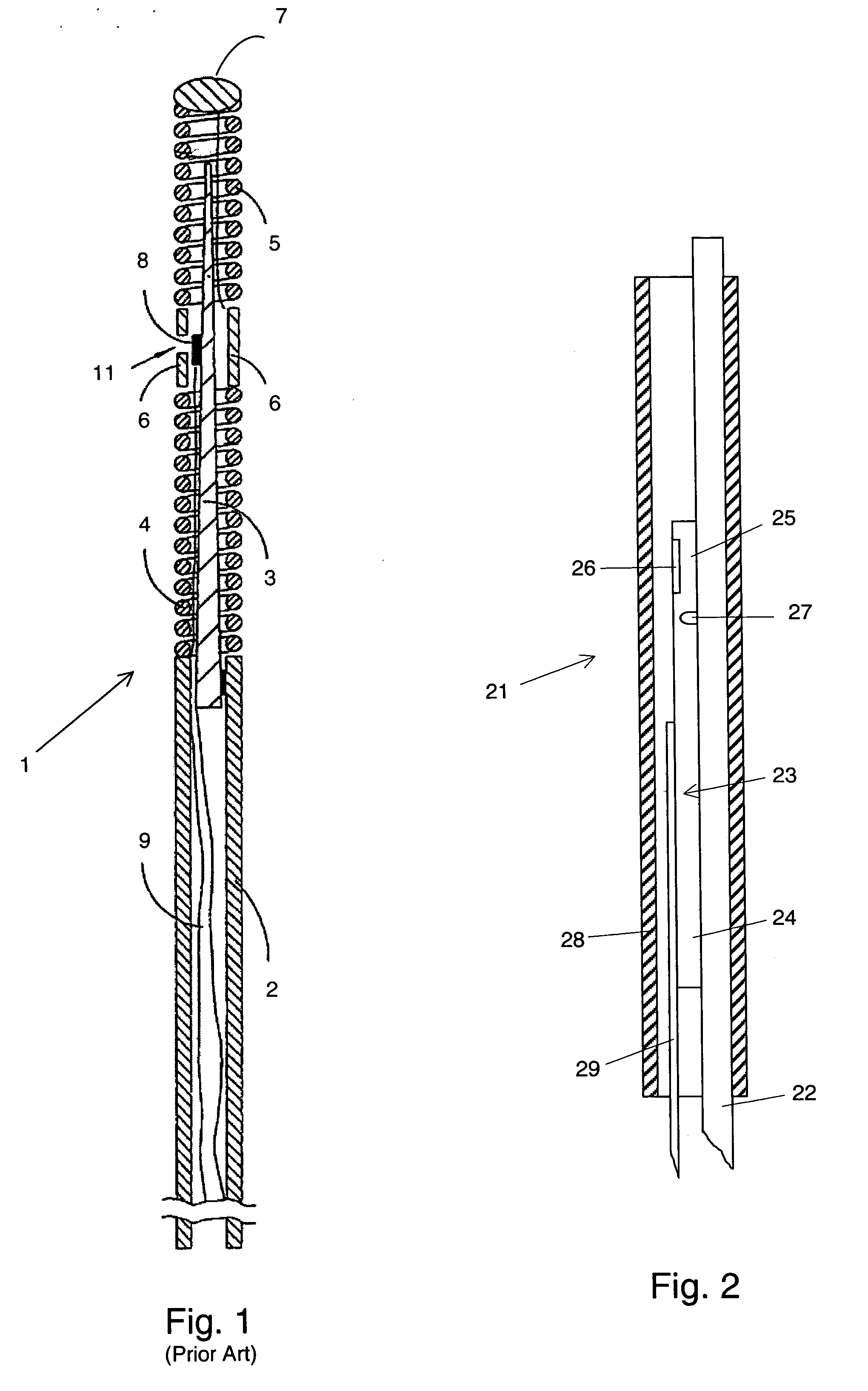
[0015] For better understanding of the context in which a sensor chip according to the present invention is going to be used, a sensor and guide wire assembly 1 of a conventional design is illustrated in FIG. 1. The sensor guide 1 comprises a hollow tube 2, a core wire 3, a first coil 4, a second coil 5, a jacket or sleeve 6, a dome-shaped tip 7, a sensor element or chip 8, and one or several electrical leads 9. The proximal end of the first coil 4 is attached to the distal end of the hollow tube 2, while the distal end of the first coil 4 is attached to the proximal end of the jacket 6. The proximal end of the second coil 5 is connected to the distal end of the jacket 6, and the dome-shaped tip 7 is attached to the distal end of the second coil 5. The core wire 3 is at least partly disposed inside the hollow tube 2 such that the distal portion of the core wire 3 extends out of the hollow tube 2 and into the second coil 5. The sensor element 8 is mounted on the core wire 3 at the po...
PUM
| Property | Measurement | Unit |
|---|---|---|
| thickness | aaaaa | aaaaa |
| width | aaaaa | aaaaa |
| depth | aaaaa | aaaaa |
Abstract
Description
Claims
Application Information
 - R&D
- Intellectual Property
- Life Sciences
- Materials
- Tech Scout
- Unparalleled Data Quality
- Higher Quality Content
- 60% Fewer Hallucinations
Browse by: Latest US Patents, China's latest patents, Technical Efficacy Thesaurus, Application Domain, Technology Topic, Popular Technical Reports.
© 2025 PatSnap. All rights reserved.Legal|Privacy policy|Modern Slavery Act Transparency Statement|Sitemap|About US| Contact US: help@patsnap.com


