Sensor and guide wire assembly

a technology of guide wire and sensor, which is applied in the direction of sensors, catheters, diagnostics, etc., can solve the problems of so-called bending artefacts, and achieve the effect of making the manufacturing of a sensor and a guide wire assembly simple and cheaper

Active Publication Date: 2007-05-29
ST JUDE MEDICAL COORDINATION CENT
View PDF10 Cites 37 Cited by
  • Summary
  • Abstract
  • Description
  • Claims
  • Application Information

AI Technical Summary

Benefits of technology

[0010]An object of the present invention is to provide a new and improved design for a jacket or sleeve, which is a member of a sensor and guide wire assembly, in such a way that, when a sensor chip is mounted in the jacket or sleeve, the sensor and guide wire assembly will have the same or better characteristics regarding resistance against bending artefacts. Preferably, the sensor and guide wire assembly should at the same time be easier and thereby cheaper to manufacture.
[0013]By arranging the sensor chip and the core wire in separate compartments in a jacket, the sensor chip is virtually independent of movements of the core wire; and in particular bending deformations of the core wire will not be transferred to the sensor chip. By this arrangement, it is not necessary to provide the core wire with a special mounting structure, such as a recess or a flattened portion. In comparison with sensor and guide wire assemblies according to the prior art, this arrangement allows the manufacturing of a sensor and guide wire assembly to be made simpler and cheaper.

Problems solved by technology

As is recognized in U.S. Pat. Nos. 6,112,598 and 6,167,763, which also are assigned to the present assignee, a potential problem with this kind of guide wire mounted sensor is the occurrence of so-called bending artefacts.
By the provision of this articulated portion, the pressure sensitive portion of the sensor element is not constrained to adapt to bending deformations of the core wire, which prevents such deformations from being transferred to the pressure sensitive device.

Method used


Image

  • Sensor and guide wire assembly
  • Sensor and guide wire assembly
  • Sensor and guide wire assembly

Examples


second embodiment

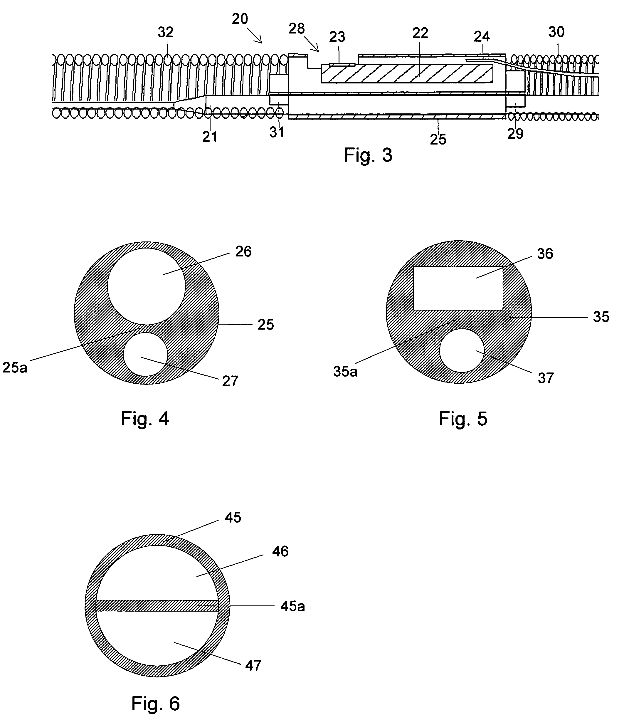
[0033]As was indicated above, the shape of a through opening in a jacket or sleeve can according to the present invention be adapted to the shape of the member to be positioned therein. FIG. 5 illustrates a sleeve or jacket 35, in which two through openings 36, 37 have been created. Here the first through opening 36 has been given a rectangular cross-section, which is adapted to a rectangular cross-section of a sensor chip (not shown in the figure). Like the embodiment shown in FIG. 4, the second through opening 37 has been given a circular cross-section in order to fit to a circular cross-section of a core wire (not shown in the figure), but other cross-section configurations are also possible. A rectangular cross-section, adapted to a core wire having a corresponding cross-section, could, for example, be advantageous in that it would prevent the core wire from rotating inside the jacket.

[0034]The through openings shown in FIGS. 4 and 5 are preferably made by drilling, punching or ...

fourth embodiment

[0035]FIGS. 7 and 8 illustrate a jacket 55 according to the present invention. This embodiment also includes an aperture 58 through which pressure may be sensed. This embodiment includes two crimps 57a and 57b in order to retain the core wire (not shown) in the lower portion of the jacket 55. Crimps 57a and 57b include members 55a and 55b, respectively, which protrude from the inner surface of the jacket into the central portion of the jacket in order to retain the core wire (not shown) in a location separate from the location of the sensor chip (not shown).

fifth embodiment

[0036]FIG. 9 illustrates a jacket 65 according to the present invention. This embodiment is a variation of the embodiment shown in FIGS. 7 and 8 and includes a crimp 67a at an end portion of the jacket 65. This embodiment also includes a member 65a which protrudes from an inner surface of the jacket toward a central portion of the jacket to retain the core wire (not shown) separate from the sensor chip (not shown).


PUM

PropertyMeasurementUnit
diameteraaaaaaaaaa
inner diameteraaaaaaaaaa
elasticaaaaaaaaaa

Abstract

The invention relates to a sensor and guide wire assembly (20) for intravascular measurements of physiological variables in a living body, comprising a core wire (21) and a sensor element (22). The sensor and guide wire assembly (20) comprises further a jacket (25; 35; 45) provided with a first opening (26; 36; 46), in which at least a portion of the sensor element (22) is arranged, and a second opening (27; 37; 47), in which a portion of the core wire (21) is arranged, the first opening (26; 36; 46) and the second opening (27; 37; 47) being separated from each other.

Description

FIELD OF THE INVENTION[0001]The present invention relates generally to sensor and guide wire assemblies, in which a sensor element is mounted at the distal end of a guide wire for intravascular measurements of physiological variables in a living body, and in particular to the mounting arrangement of the sensor element.BACKGROUND OF THE INVENTION[0002]Sensor and guide wire assemblies in which a sensor is mounted at the distal end of a guide wire are known. In U.S. Pat. No. Re. 35,648, which is assigned to the present assignee, an example of such a sensor and guide wire assembly is disclosed, where a sensor guide comprises a sensor element, an electronic unit, a signal transmitting cable connecting the sensor element to the electronic unit, a flexible tube having the cable and the sensor element disposed therein, a solid metal wire, and a coil attached to the distal end of the solid wire. The sensor element comprises a pressure sensitive device, e.g. a membrane, with piezoresistive el...

Claims


Application Information

Patent Timeline
Patent Type & Authority Patents(United States)
IPC IPC(8): G01L7/00A61B5/0215G01L1/18G01L9/06
CPCA61B5/0215A61B5/6851G01L1/18
Inventor TULKKI, SAULI
Owner ST JUDE MEDICAL COORDINATION CENT
Why Eureka
Try Eureka