Lawn maintenance system

Inactive Publication Date: 2006-02-07
SIMMONS WILLIE
View PDF10 Cites 22 Cited by
  • Summary
  • Abstract
  • Description
  • Claims
  • Application Information

AI Technical Summary

Benefits of technology

[0021]It is therefore an object of the present invention to provide a new and improved lawn maintenance system which has all of the advantages of the prior art containers of known designs and configurations and none of the disadvantages.
[0022]It is another object of the present invention to provide a new and improved lawn maintenance system which may be easily and efficiently manufactured and marketed.
[0023]It is further an object of the present invention to provide

Problems solved by technology

While these devices fulfill their respective, particular objectives and requirements, the aforementioned patents do not desc

Method used


Image

  • Lawn maintenance system
  • Lawn maintenance system
  • Lawn maintenance system

Examples


Example

INVENTOR COMMENTS

[0035]The same reference numerals refer to the same parts throughout the various Figures.

DESCRIPTION OF THE PREFERRED EMBODIMENT

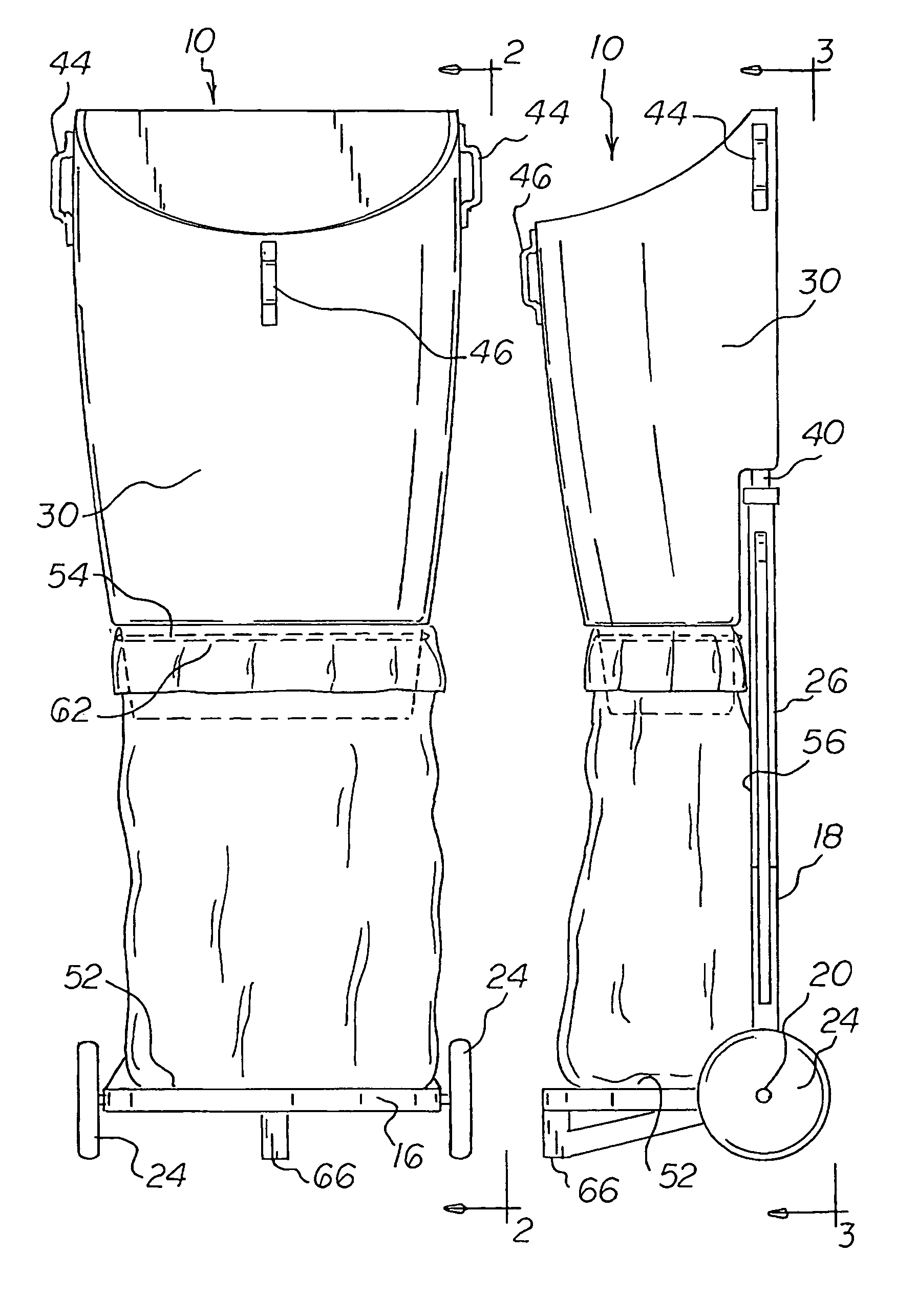
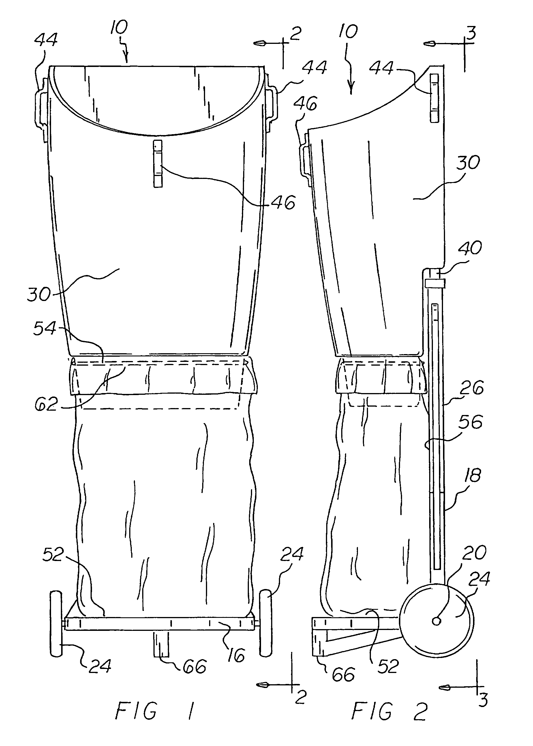
[0036]With reference now to the drawings, and in particular to FIG. 1 thereof, the preferred embodiment of the new and improved lawn maintenance system embodying the principles and concepts of the present invention and generally designated by the reference numeral 10 will be described.

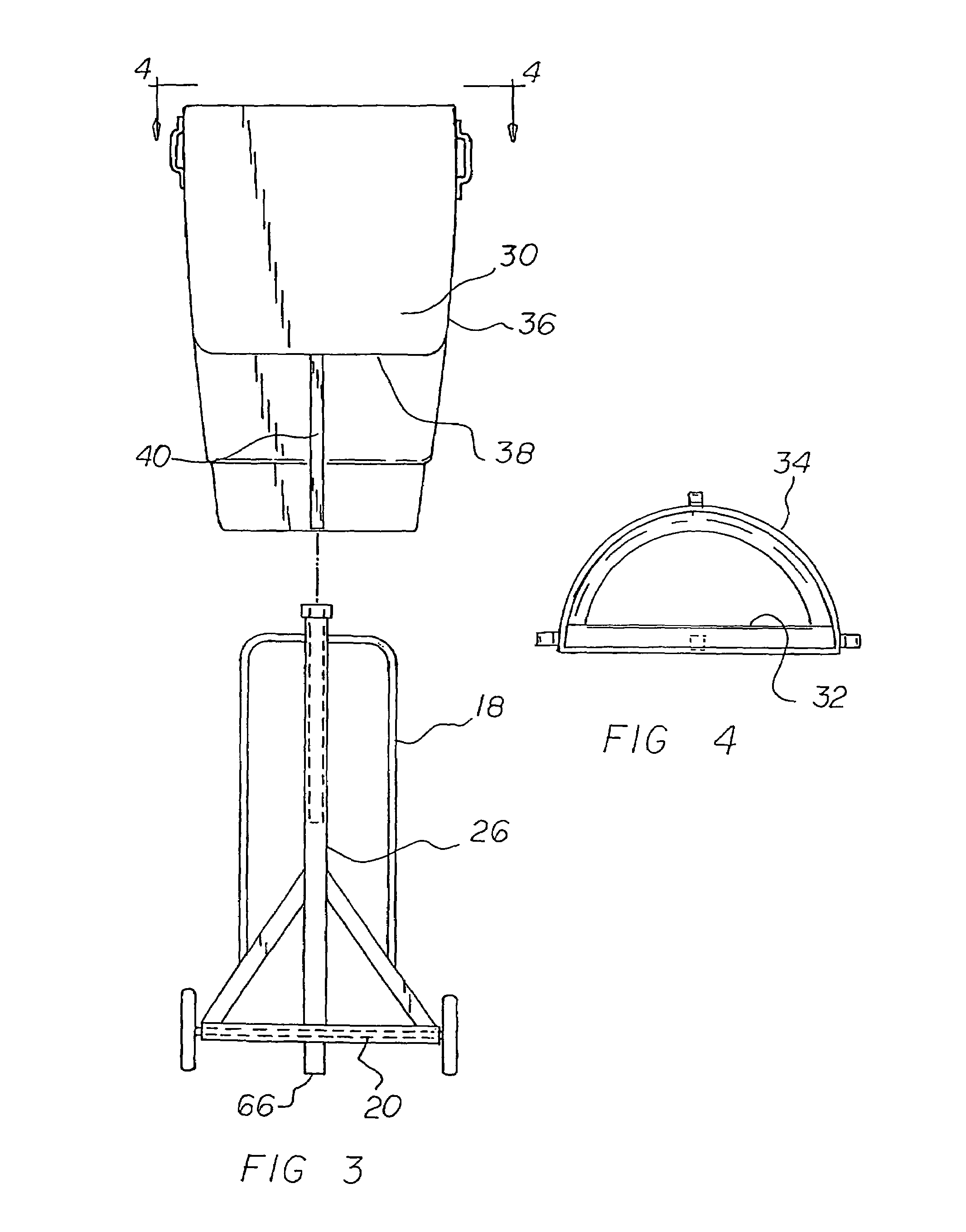
[0037]The present invention, the lawn maintenance system 10 is comprised of a plurality of components. Such components in their broadest context include a frame, a pair of axially spaced wheels, a hollow tube, and a funnel. Such components are individually configured and correlated with respect to each other so as to attain the desired objective.

[0038]First provided is a frame 14. The frame has a small horizontal section 16 and a large vertical section 18. The horizontal and vertical sections are secured together at a juncture 20.

[0039]A pair of axially spaced...


PUM

PropertyMeasurementUnit
Elevationaaaaaaaaaa

Abstract

A frame has a small horizontal section and a large vertical section and a juncture there between. A pair of axially spaced wheels is provided at the juncture. A hollow tube extends upwardly from adjacent the horizontal section to a location above the vertical section. A funnel with a back face and a front face is provided. The funnel also has an open upper end and an open lower end. The back face is formed with a ledge. A rod extends downwardly from the ledge. The rod is selectively positioned between an operative position and an inoperative position. In the operative position the rod is within the hollow tube. In the inoperative position the rod is separated from the hollow tube for storage purposes.

Description

BACKGROUND OF THE INVENTION[0001]1. Field of the Invention[0002]The present invention relates to a lawn maintenance system and more particularly pertains to raking and bagging leaves and other lawn debris and refuse in a convenient manner.[0003]2. Description of the Prior Art[0004]The use of containers of known designs and configurations is known in the prior art. More specifically, containers of known designs and configurations previously devised and utilized for the purpose of assisting a user in containing debris through known methods and apparatuses are known to consist basically of familiar, expected, and obvious structural configurations, notwithstanding the myriad of designs encompassed by the crowded prior art which has been developed for the fulfillment of countless objectives and requirements.[0005]By way of example, U.S. Pat. No. 754,580 issued Mar. 15, 1904 to Madden relates to a bag holder. U.S. Pat. No. 3,893,699 issued Mar. 15, 1904 to Morris relates to a refuse bag h...

Claims


Application Information

Patent Timeline
IPC IPC(8): A63B55/08A63B55/60
CPCB65B67/1238B65F1/10B65F1/1468B65F1/1415B65F2240/138
Inventor SIMMONS, WILLIE
Owner SIMMONS WILLIE
Why Eureka
Try Eureka