Cash register alarm system

Inactive Publication Date: 2006-10-03
POLLARD WILLIAM REGINALD
View PDF10 Cites 9 Cited by
  • Summary
  • Abstract
  • Description
  • Claims
  • Application Information

AI Technical Summary

Benefits of technology

[0016]It is another object of the present invention to provide a new cash register alarm system which may be easily and efficiently manufactured and marketed.
[0017]It is a further object of the present invention to provide a new cash register alarm system which is of a durable and reliable construction.
[0018]An even further object of th

Problems solved by technology

While these devices fulfill their respective, particular objectives and requireme

Method used


Image

  • Cash register alarm system
  • Cash register alarm system
  • Cash register alarm system

Examples


Example

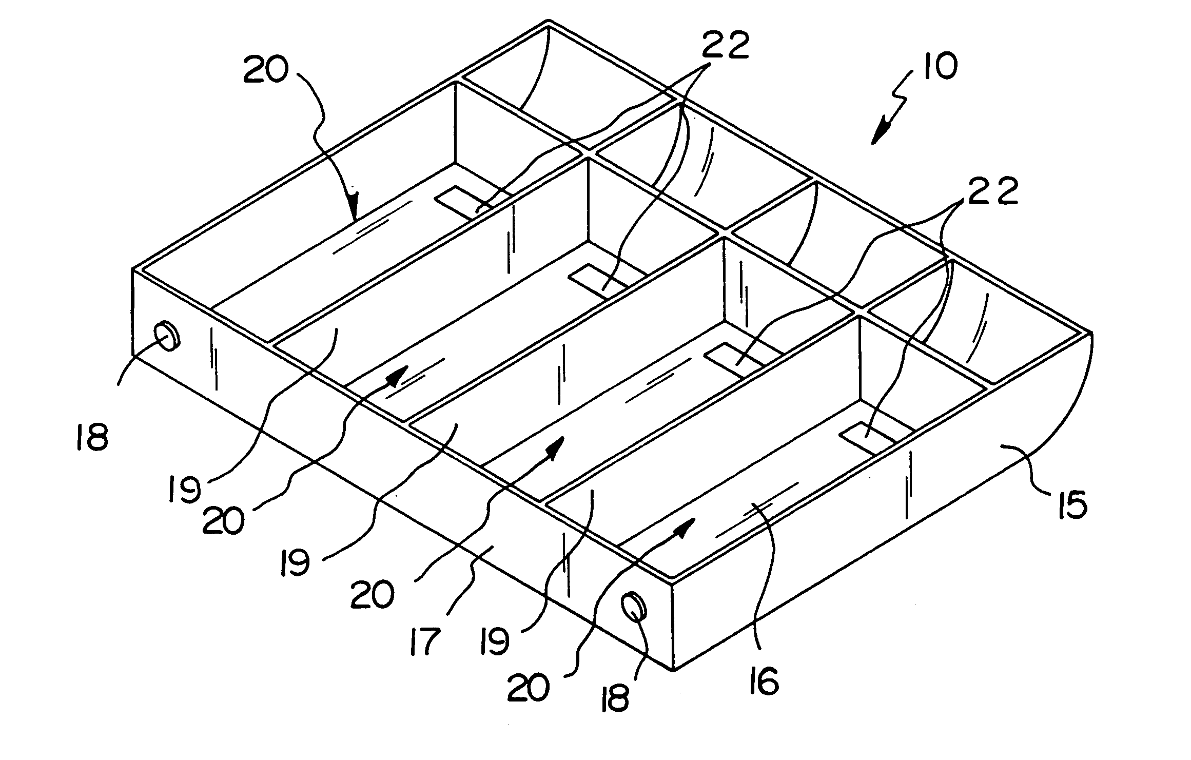
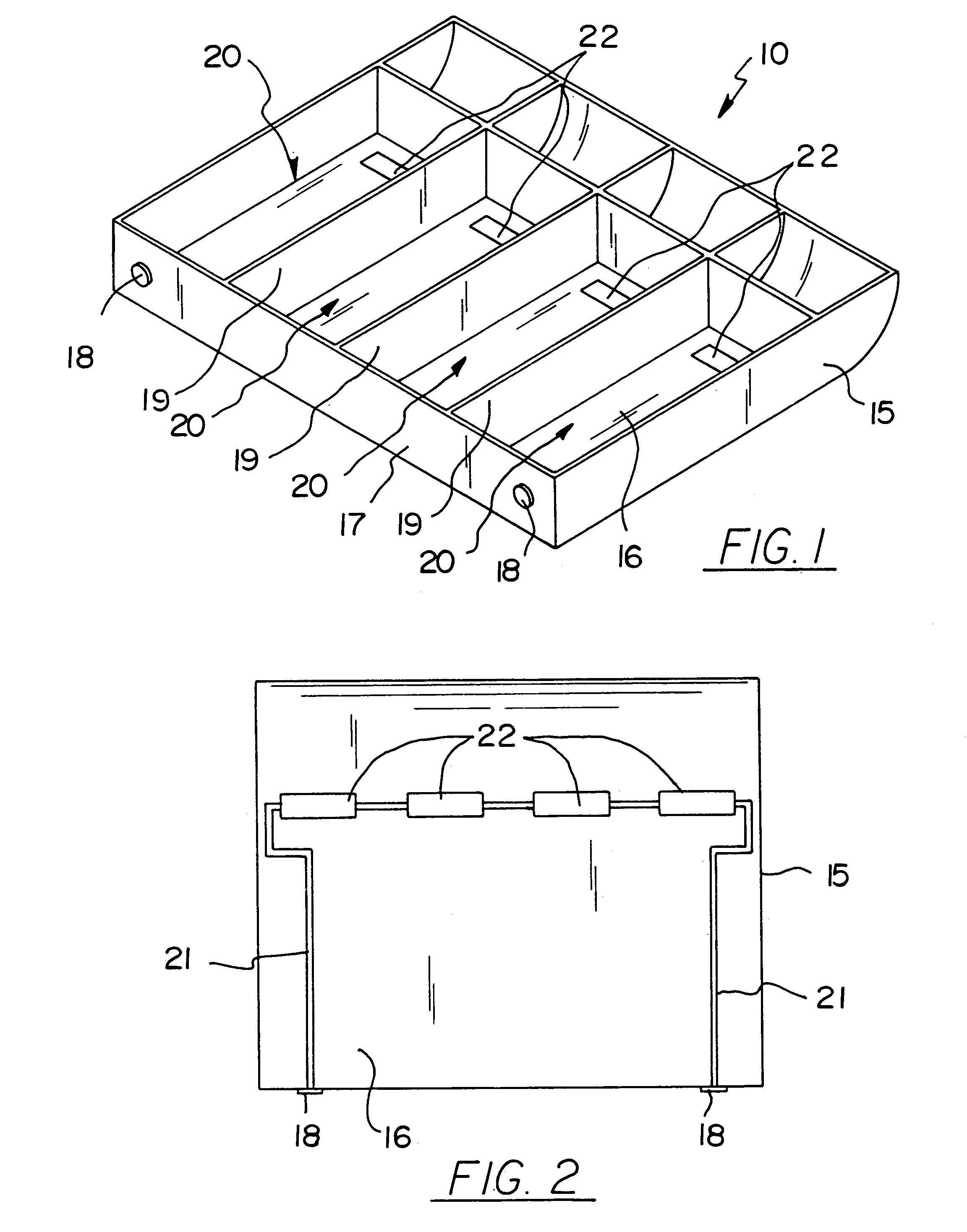
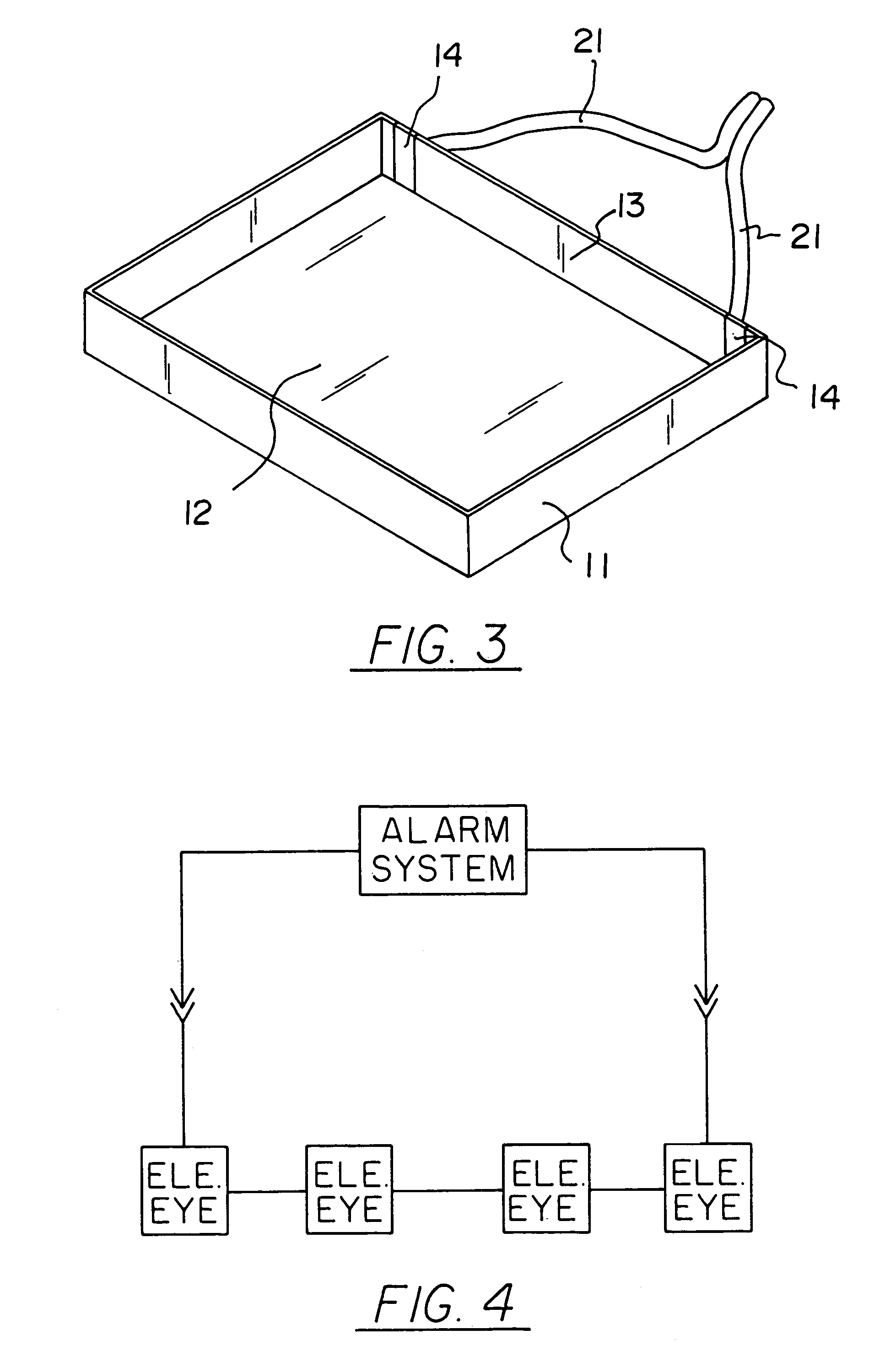
[0030]With reference now to the drawings, and in particular to FIGS. 1 through 4 thereof, a new cash register alarm system embodying the principles and concepts of the present invention and generally designated by the reference numeral 10 will be described.

[0031]As best illustrated in FIGS. 1 through 4, the cash register alarm system 10 generally comprises a cash drawer 11 having a back wall 13 and a bottom wall 12, and further comprises a tray 15 having a bottom wall 16 and a back wall 17 and being removeably disposed upon the bottom wall 12 of the cash drawer 11 with the tray 15 further having a plurality of partitions 19 spaced apart and forming compartments 20 in the tray 15. A plurality of sensors 22 are conventionally disposed in the compartments 20 and in the bottom wall 16 of the tray 15 for detecting whether the compartments 20 have any paper money contained therein. A plurality of electrical current contact members 14,18 are securely and conventionally disposed upon the ba...


PUM


Abstract

A cash register alarm system for sounding an alarm to the police without delay. The cash register alarm system includes a cash drawer having a bottom wall and a back wall, and also includes a tray having a bottom wall and a back wall and plurality of partitions spaced apart and forming compartments therebetween, and further includes a plurality of sensors disposed in the compartments in the bottom wall of the tray, and also includes a plurality of electrical current contact members disposed upon the back walls of the cash drawer and the tray. More than one compartment without paper money will expose the sensors to light which will acutate the alarm system to the police.

Description

BACKGROUND OF THE INVENTION[0001]1. Field of the Invention[0002]The present invention relates to a silent alarm system for a cash drawer and more particularly pertains to a new cash register alarm system for sounding an alarm to the police without delay.[0003]2. Description of the Prior Art[0004]The use of silent alarm system for a cash drawer is known in the prior art. More specifically, silent alarm system for a cash drawer heretofore devised and utilized are known to consist basically of familiar, expected and obvious structural configurations, notwithstanding the myriad of designs encompassed by the crowded prior art which have been developed for the fulfillment of countless objectives and requirements.[0005]Known prior art includes U.S. Pat. No. 5,512,877; U.S. Pat. No. 3,618,060; U.S. Pat. No. 3,828,166; U.S. Pat. No. 4,070,564; U.S. Pat. No. 4,054,752; and U.S. Pat. No. Des. 258,365.[0006]While these devices fulfill their respective, particular objectives and requirements, th...

Claims


Application Information

Patent Timeline
IPC IPC(8): G08B13/14
CPCG07G1/0027G07G3/003G08B13/1481E05G1/06E05G1/10
Inventor POLLARD, WILLIAM REGINALD
Owner POLLARD WILLIAM REGINALD
Why Eureka
Try Eureka