Head covering

a head covering and head technology, applied in the field of head coverings, can solve the problem of not disclosing a new head covering, etc., and achieve the effect of convenient and convenient use and easy and convenient setup

Inactive Publication Date: 2006-02-14
CABRERA JUAN C
View PDF7 Cites 84 Cited by
  • Summary
  • Abstract
  • Description
  • Claims
  • Application Information

AI Technical Summary

Benefits of technology

[0011]Still another object of the present invention is to provide a new head covering for shielding the head neck, face and ears from the harsh elements of the environment without obstructing the user's vision.
[0012]Still yet another object of the present invention is to provide a new head

Problems solved by technology

While these devices fulfill their respective, particular objectives and re

Method used


Image

  • Head covering
  • Head covering
  • Head covering

Examples


Embodiment Construction

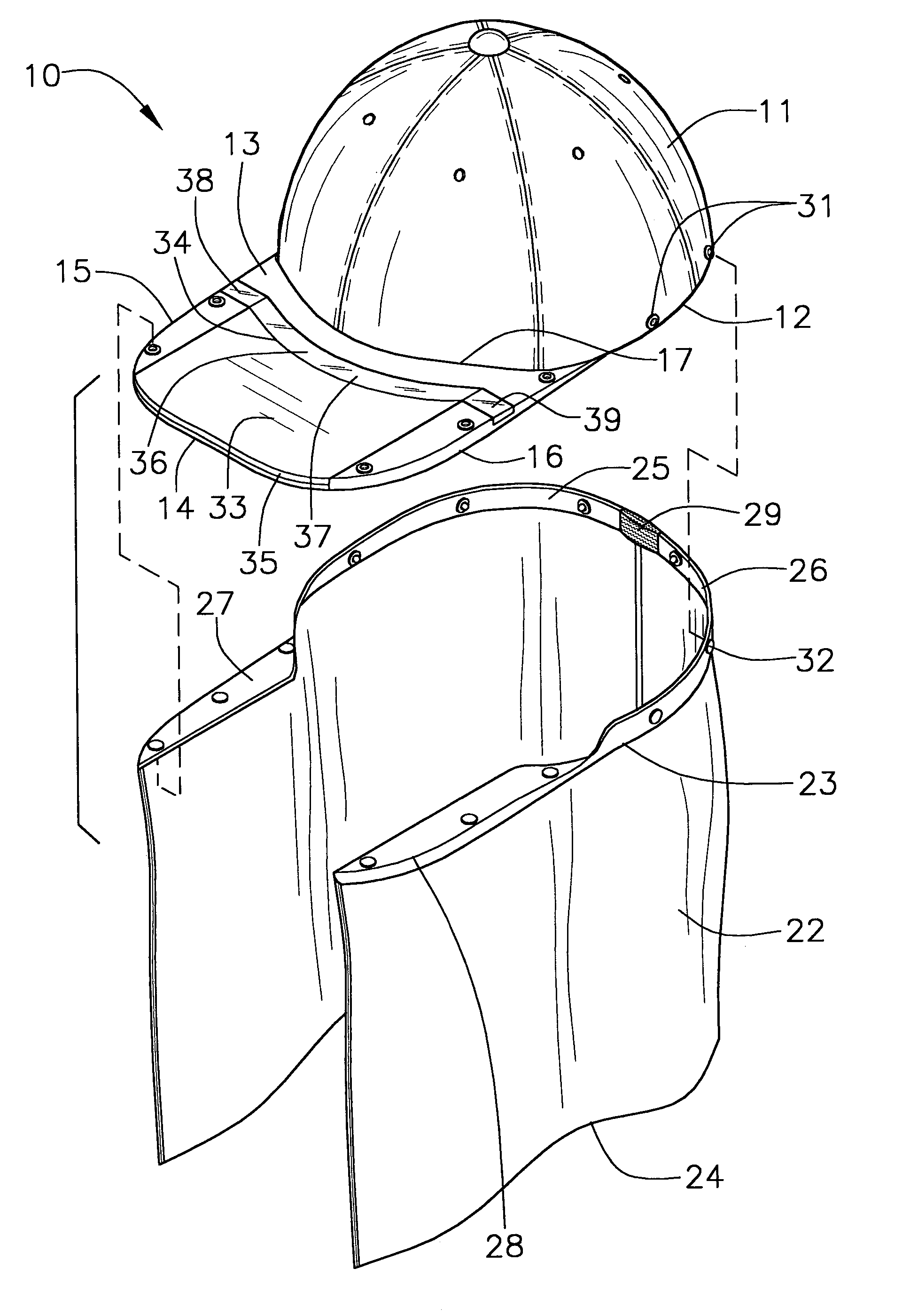
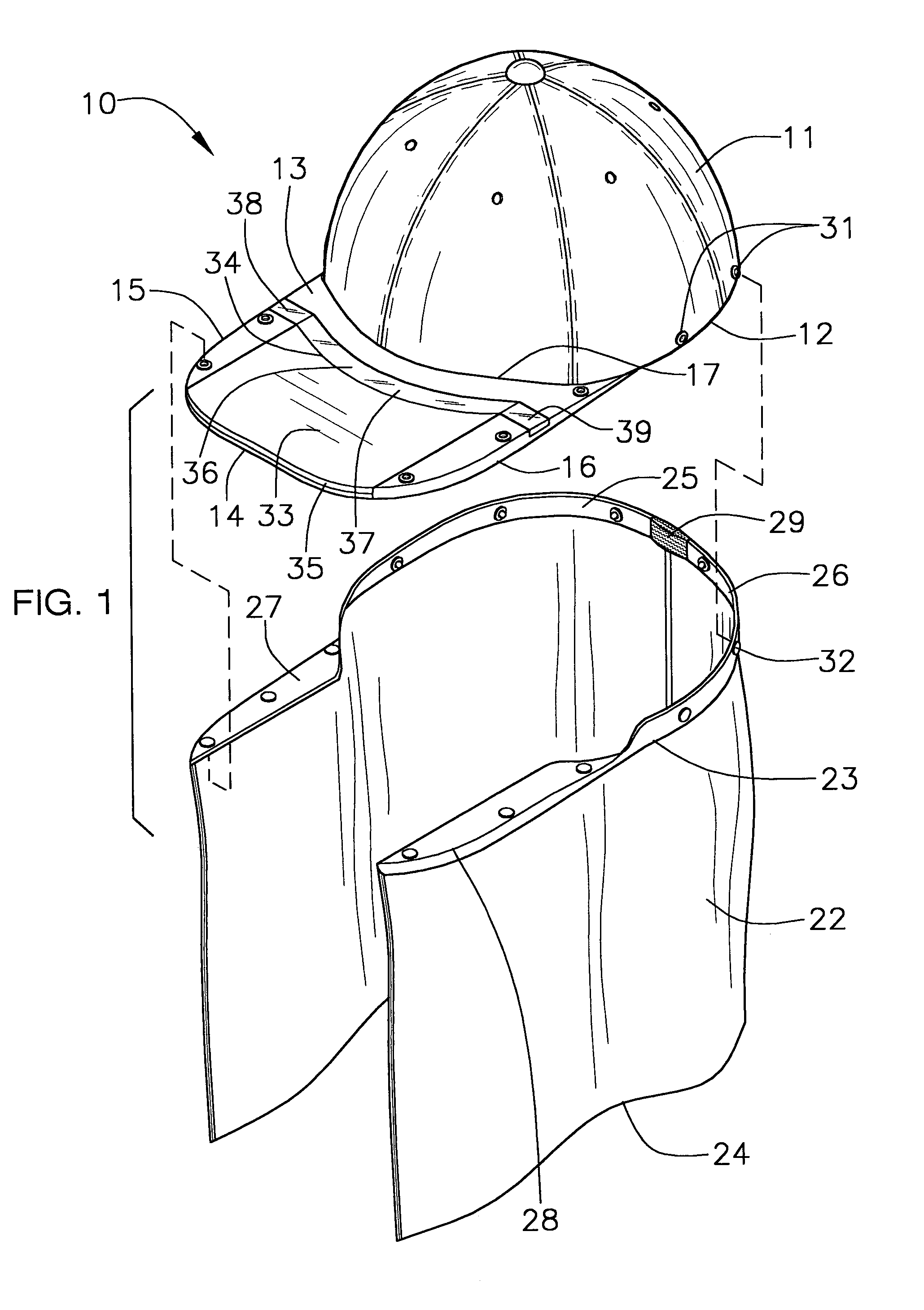
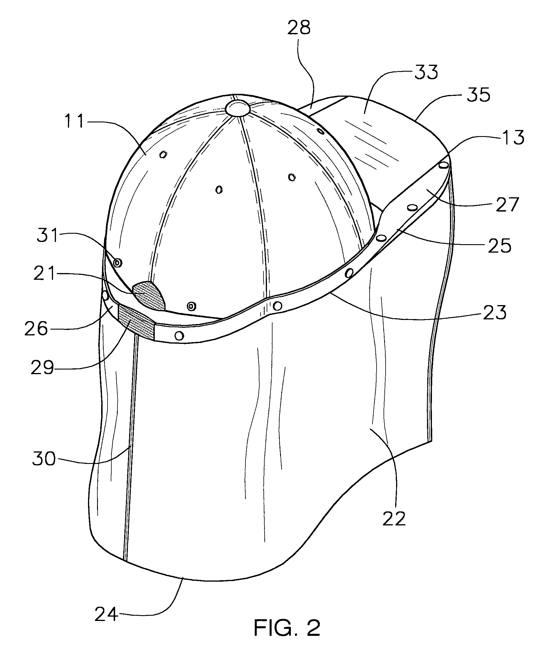
[0020]With reference now to the drawings, and in particular to FIGS. 1 through 4 thereof, a new head covering embodying the principles and concepts of the present invention and generally designated by the reference numeral 10 will be described.

[0021]As best illustrated in FIGS. 1 through 4, the head covering 10 generally comprises a cap including a head cover member 11 and a bill 13. The bill 13 is securely attached and sewn to the head cover member 11, and extends forwardly therefrom, and has a top side, and further has a recessed portion 18-20 being disposed in the top side. The recessed portion 18-20 includes a mirror-receiving recessed portion 18 extending through a portion of a front edge 14 of the bill 13 and being spaced from side edges 15,16 of the bill 13 and extending along and being spaced from a portion of a back edge 17 of the bill 11, and also includes handle-receiving recessed portions 19,20 being disposed through the side edges 15,16 of the bill 11 and being continuo...


PUM


Abstract

A head covering for shielding the head neck, face and ears from the harsh elements of the environment with obstructing the user's vision. The head covering includes a cap including a head cover member and a bill; and also includes a shroud assembly including a shroud being removably depending from the cap; and further includes fastening members for fastening the shroud to the cap; and also includes a mirror assembly including a mirror being hingedly attached to the bill for allowing a user to view about oneself while wearing the head covering.

Description

BACKGROUND OF THE INVENTION[0001]1. Field of the Invention[0002]The present invention relates to head coverings and more particularly pertains to a new head covering for shielding the head neck, face and ears from the harsh elements of the environment with obstructing the user's vision.[0003]2. Description of the Prior Art[0004]The use of head coverings is known in the prior art. More specifically, head coverings heretofore devised and utilized are known to consist basically of familiar, expected and obvious structural configurations, notwithstanding the myriad of designs encompassed by the crowded prior art which have been developed for the fulfillment of countless objectives and requirements.[0005]Known prior art includes U.S. Pat. No. 899,334; U.S. Pat. No. 5,448,778; U.S. Pat. No. 5,081,717; U.S. Pat. No. Des. 401,393; U.S. Pat. No. Des. 363,812; and U.S. Pat. No. Des. 380,591.[0006]While these devices fulfill their respective, particular objectives and requirements, the aforeme...

Claims


Application Information

Patent Timeline
IPC IPC(8): A42B1/06
CPCA42B1/062A42B1/24A42B1/067A42B1/0182A42B1/0187
Inventor CABRERA, JUAN C.
Owner CABRERA JUAN C
Why Eureka
Try Eureka