
Aerodynamic sliders with curved side surface

Active Publication Date: 2006-02-14
SEAGATE TECH LLC
View PDF13 Cites 2 Cited by
  • Summary
  • Abstract
  • Description
  • Claims
  • Application Information

AI Technical Summary

Benefits of technology

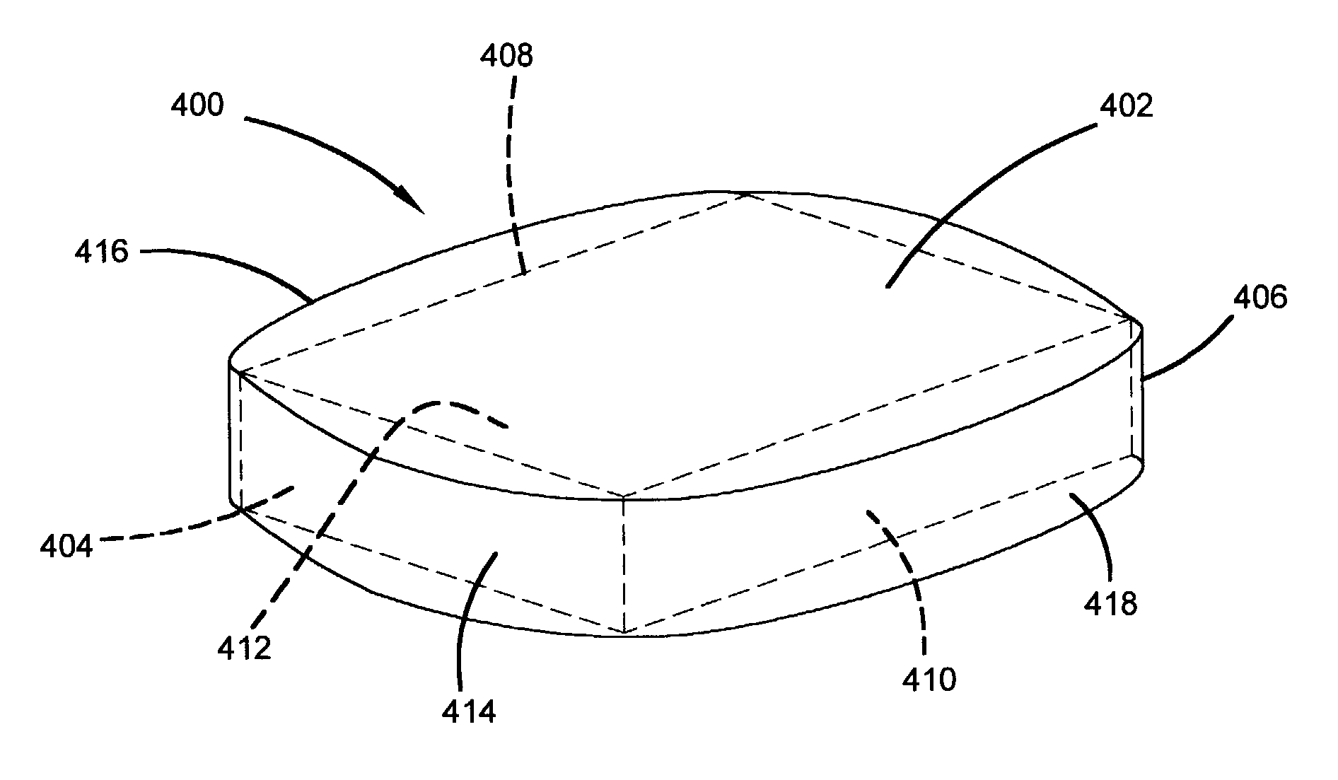
[0008]In one embodiment, an aerodynamic slider has at least one side surface that is continuously curved between leading and trailing surfaces. The one side surface is curved to substantially eliminate off-track forces on the side surface due at all design skew orientations.

Problems solved by technology

However at non-zero skew orientations (either positive or negative skew), the pattern of shed vortices is not symmetrical, leading to asymmetrical off-track forces on the slider that tend to shift the slider radially.
If these asymmetrical off-track forces are at the structural mode of the suspension, they may cause non-repeatable runout (NRRO) in the form of radial vibration in the slider and suspension.

Method used


Image

  • Aerodynamic sliders with curved side surface
  • Aerodynamic sliders with curved side surface
  • Aerodynamic sliders with curved side surface

Examples


Embodiment Construction

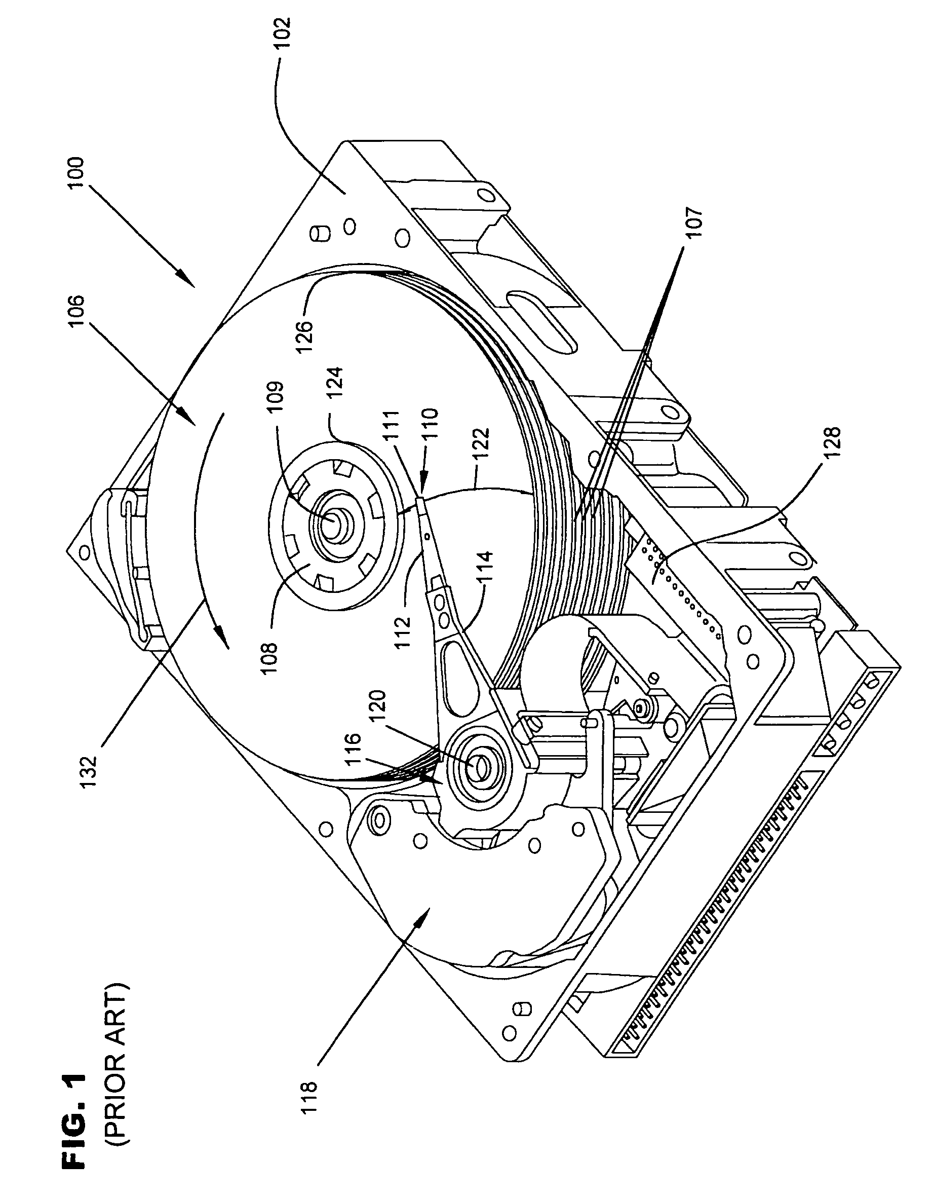
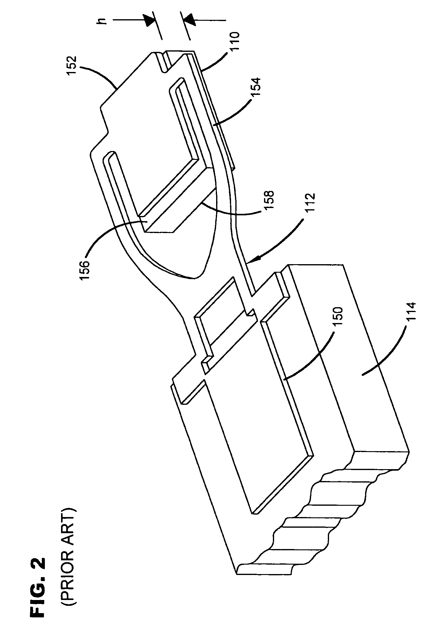
[0020]FIG. 1 is a perspective view of a disc drive 100 in which a slider fabricated according to the present invention is useful. Disc drive 100 includes a housing with a base 102 and a top cover (not shown). Disc drive 100 further includes a disc pack 106, which is mounted on a spindle motor (not shown) by a disc clamp 108 for rotation in the direction of arrow 132. Disc pack 106 includes a plurality of individual discs 107, which are mounted for co-rotation about central axis 109. Each disc surface has an associated slider 110 that is mounted in disc drive 100 for communication with the confronting disc surface. Slider 110 is arranged to fly above the associated disc surface of an individual disc of disc pack 106, and carries a transducing head 111 arranged to write data to, and read data from, concentric tracks on the confronting disc surface. In the example shown in FIG. 1, sliders 110 are supported by suspensions 112 which are in turn attached to track accessing arms 114 of an ...


PUM

PropertyMeasurementUnit
Forceaaaaaaaaaa

Abstract

An aerodynamic slider has at least one side surface that is continuously curved between the leading and trailing surfaces to substantially eliminate off-track forces on the side surface due to changing skew orientations. A slider profile is modeled, and a numerical simulation of airflow on the modeled profile is generated for each of a plurality of skew orientations within a range of skew orientations at which the slider will fly. The modeled slider profile is repeatedly adjusted based on the numerical simulations until a vibration analysis on the modeled profile indicates vibration does not exceed a predetermined minimum.

Description

CROSS-REFERENCE TO RELATED APPLICATION[0001]This application claims priority of U.S. Provisional Application No. 60 / 380,809 filed May 14, 2002 for “Aerodynamic Slider Profiling for Disc Drives”.FIELD OF THE INVENTION[0002]This invention concerns aerodynamic sliders that are supported by airflow to fly small distances adjacent a moving surface, and particularly to profiled sliders that minimize effects of off-track force on the slider.BACKGROUND OF THE INVENTION[0003]Magnetic disc drive storage devices store digital data on rotatable magnetizable disc surfaces. Data are written to and read from concentric tracks on the disc surface by read and write transducers, usually called “heads”, that are carried on the slider. Each slider is mounted to a flexible suspension that is supported by an actuator arm of an actuator member, such as an E-block. The actuator member is rotated by a voice coil actuator motor to move the slider and head along an arcuate path that is oriented generally radi...

Claims


Application Information

Patent Timeline
IPC IPC(8): G11B5/60G11B15/64G11B17/32G11B21/20G11B21/21
CPCG11B5/6005Y10T29/49036
Inventor TADEPALLI, SRINIVASRAO, RAM M.
Owner SEAGATE TECH LLC
Learn More