
Optical disk and method of recording data in the same

a high-density optical disk and optical disk technology, applied in the direction of digital signal error detection/correction, electronic editing digitised analogue information signals, instruments, etc., can solve the problems of inability to define the optical recording/reproducing method or the disk structure with respect to such defective area, the method of processing such defective area and the disk structure related thereto have not been defined, etc., to achieve the effect of improving recording and reproducing performance and ensuring compatibility between disks

Active Publication Date: 2006-02-14
SAMSUNG ELECTRONICS CO LTD +1
View PDF8 Cites 15 Cited by
  • Summary
  • Abstract
  • Description
  • Claims
  • Application Information

AI Technical Summary

Benefits of technology

[0008]To solve the above-described problems, it is a first object of the present invention to provide an optical disk in which linking occurs at a position where overwriting starts and in which recording end data for terminating the recording is recorded at a position where overwriting ends, and a method of recording data in the optical disk, thereby securing compatibility between disks and disk drives and improving recording and reproducing performance on high-density optical disks.
[0009]It is a second object of the present invention to provide an optical disk in which when a defective area is produced during overwriting, recoding end data for terminating the recording is recorded in front of the defective area and linking occurs behind the defective area, and a method of recording data in the optical disk, thereby realizing smooth, continuous recording and reproducing.

Problems solved by technology

However, an optical recording / reproducing method or disk structure with respect to such defective area is not defined.
Accordingly, processing on defective areas can be different depending upon manufacturers of disks or recording and reproducing apparatuses, thereby causes disks to be incompatible with recording and reproducing apparatuses.
This problem may commonly occur in CD family recording media, DVD family recording media, and HD-DVD family recording media.
However, for HD-DVDs having a capacity of 23 GB or greater which will be produced in the future, a method of processing a defective area and a disk structure related thereto have not never been defined.
Moreover, a recording method at positions where overwriting starts and ends when overwriting occurs in a partial area in a data recording area has not been defined.
Accordingly, as described above, compatibility problems occur, resulting in unreliable recording and reproducing.

Method used


Image

  • Optical disk and method of recording data in the same
  • Optical disk and method of recording data in the same
  • Optical disk and method of recording data in the same

Examples


first embodiment

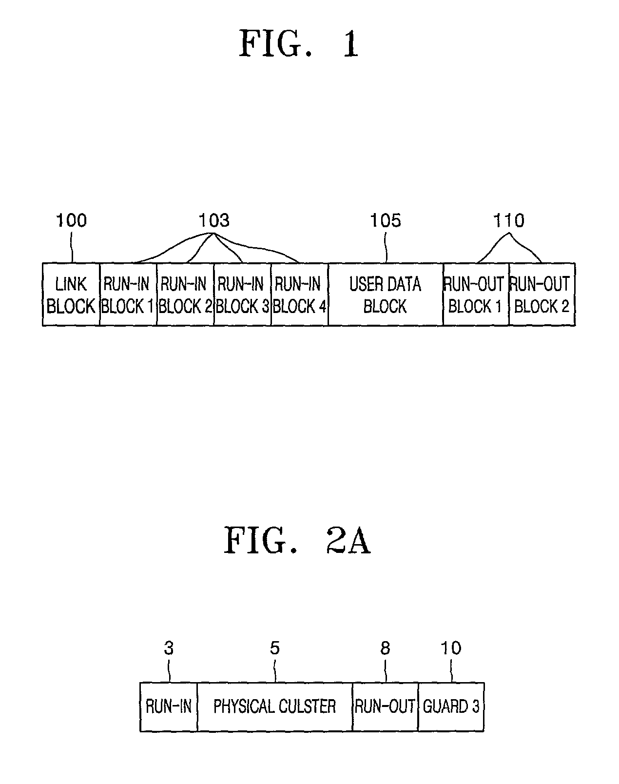
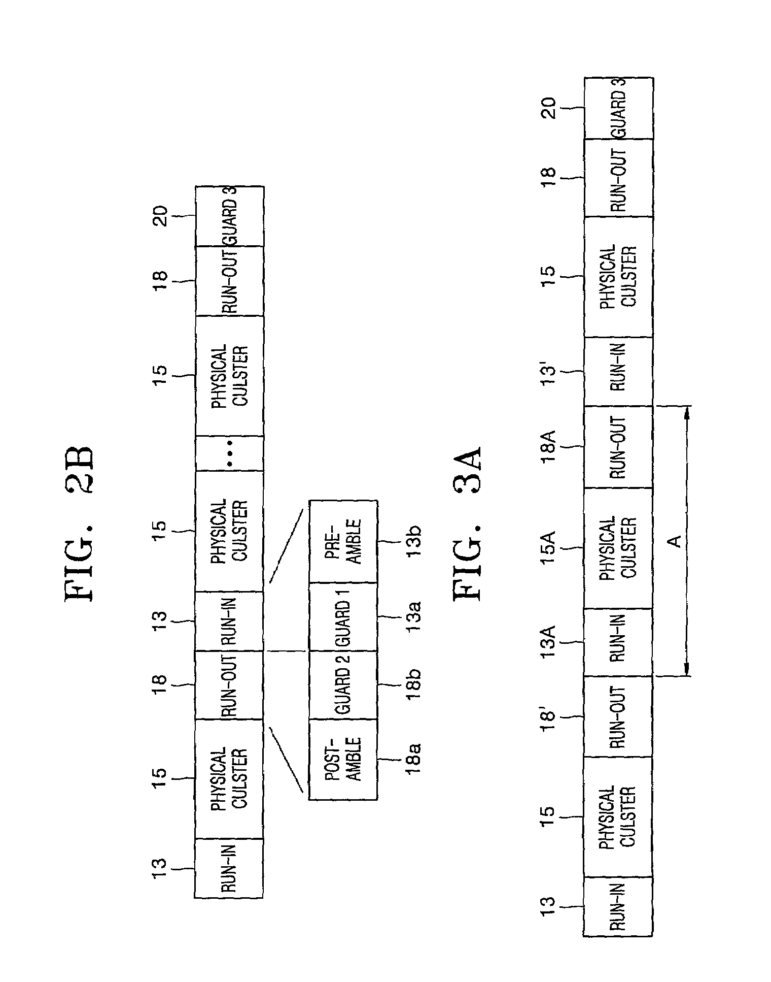
[0033]FIG. 3A shows a case where overwriting is performed on a physical cluster 15A in which data has been continuously recorded. A run-in is provided in front of each of the physical clusters, and a run-out is provided behind each of the physical clusters. A guard320 is provided at a position where recording ends. For example, when overwriting is performed in an area A in FIG. 3A, a run-in, a physical cluster, and a run-out in the overwriting area are denoted by reference characters 13A, 15A, and 18A, respectively. Here, in a method of recording data in an optical disk according to the present invention, as shown in FIG. 3B, linking occurs between a run-in 13A and a run-out 18′ in front of an overwriting area A.

[0034]Linking allows recording to be performed smoothly when overwriting erroneously starts from a portion of the run-out 18′ or a run-in 13A of FIG. 3A where overwriting should not be performed in the case where overwriting is performed on a part of a disk. In other words, ...

second embodiment

[0039]The following description concerns an optical disk and a recording method according to the present invention. FIG. 4A shows a case where a defective area 26 on which recording and reproducing cannot be performed is detected while data is continuously recorded in or reproduced from a plurality of physical clusters 25B in a recordable and / or reproducible high-density optical disk. Here, the address of the defective area 26 is recorded in a defect list field. The defective area 26 can be detected during recording, reproducing, or disk verification. Run-ins 23 and 23B are provided in front of the physical clusters 25 and 25B, respectively, and run-outs 28′ and 28B are provided behind the physical clusters 25 and 25B.

[0040]A recording method according to the second embodiment of the present invention is applied when data is overwritten in a recording area in which data has been recorded in an optical disk including the defective area 26. In FIG. 4A, an overwriting area is denoted b...


PUM


Abstract

An optical disk and a method of recording data in the optical disk are provided. When data is overwritten on a recordable and / or reproducible optical disk, the method includes performing linking in front of a physical cluster from which overwriting starts. According to the method, when overwriting is performed on a portion of an optical disk in which data has been recorded, or when overwriting is performed on a portion including a defective area, linking is performed in front of the portion on which the overwriting is performed or behind the defective area, thereby realizing reliable data recording and reproducing.

Description

BACKGROUND OF THE INVENTION[0001]1. Field of the Invention[0002]The present invention relates to a high-density optical disk and a method of recording data in the high-density optical disk, and more particularly, to an optical disk in which data is continuously recorded and then linking is defined at a portion where an overwriting area starts, and a method of recording data in the optical disk.[0003]2. Description of the Related Art[0004]Generally, optical disks are widely employed as information recording media by optical pickup apparatuses for recording or reproducing information in a noncontact way and are classified into compact disks (CDs) and digital versatile disks (DVDs) according to information-recording capacity. Representative recordable, erasable, and reproducible optical disks are 650 MB compact disc recordables (CD-Rs), CD-rewritables (RWs), and 4.7 GB DVD-RWs. Furthermore, 23 GB high definition (HD)-DVDs are under development[0005]In the case of CD-RWs, a basic record...

Claims


Application Information

Patent Timeline
IPC IPC(8): G11B7/00G11B20/10G11B7/004G11B7/006G11B7/007G11B7/013G11B11/00G11B20/12G11B20/18G11B27/034G11B27/036
CPCG11B7/00736G11B20/1217G11B20/1883G11B27/036G11B2220/2579G11B7/24085G11B27/034G11B2020/10898G11B2020/1221G11B2020/1277G11B2220/20G11B2220/215G11B2220/216G11B2220/218G11B2220/2537G11B2220/2545G11B2220/2562G11B7/24079G11B7/004
Inventor LEE, KYUNG-GEUNPARK, IN-SIKKO, JUNG-WANUSUI, MAKOTOITO, MOTOSHI
Owner SAMSUNG ELECTRONICS CO LTD
Learn More