Magnetic tape cartridge

a magnetic tape and cartridge technology, applied in the field can solve the problems of losing compatibility with existing insufficient to meet the demands, and inability to ensure compatibility with conventional recording and reproducing devices, so as to achieve the effect of increasing the recording capacity of magnetic tape cartridges

Inactive Publication Date: 2007-12-18
HITACHT MAXELL LTD
View PDF8 Cites 3 Cited by
  • Summary
  • Abstract
  • Description
  • Claims
  • Application Information

AI Technical Summary

Benefits of technology

[0010]An object of the present invention is to provide, for solving these problems, a means to achieve high recording capacity of a magnetic tape cartridge while securing compatibility with conventional recording and reproducing devices.
[0012]In the present invention, modifying components used in conventional magnetic tape cartridges allows increased recording capacity of a magnetic tape cartridge while securing compatibility with conventional recording and reproducing devices.

Problems solved by technology

While these methods can enhance the recording capacity of the magnetic tape cartridges, they are still not enough to satisfy the demands.
However, in each of these methods, the size of existing cartridges needs to be changed, which causes a problem that compatibility with conventional recording and reproducing devices cannot be secured.
Consequently, changing the thickness or the size of cartridges beyond a certain limit means losing compatibility with the existing recording and reproducing devices.

Method used


Image

  • Magnetic tape cartridge
  • Magnetic tape cartridge
  • Magnetic tape cartridge

Examples


embodiment 1

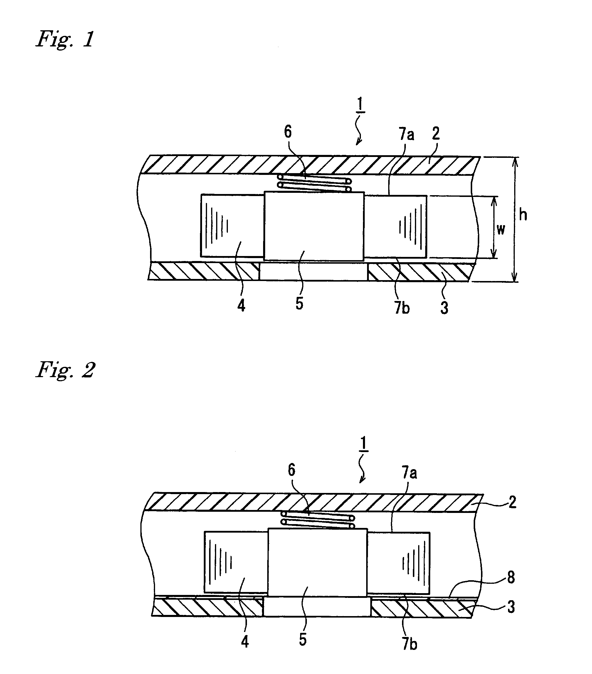
[0036]FIG. 1 is a fragmentary cross sectional view showing one example of a magnetic tape cartridge of the present invention. In FIG. 1, a cartridge 1 is composed of a top shell 2 and a bottom shell 3. A magnetic tape 4 is wound onto a reel 5, and the reel 5 is housed in between the top shell 2 and the bottom shell 3. FIG. 1 also shows the magnetic tape 4 in a stored state, in which the reel 5 is pressed toward the bottom shell 3 by a reel spring 6.

[0037]Winding surfaces 7a, 7b of the magnetic tape 4 face the top shell 2 and the bottom shell 3 through a space section. More particularly, in the present embodiment, the reel 5 does not have an upper flange nor a lower flange. Therefore, the width of the magnetic tape 4 can be enlarged proportionally by the thickness of the upper flange and the lower flange, so that the width of the magnetic tape 4 can be over 12.65 mm (½ inch), a thickness h of the cartridge 1 can be 32 mm or less and the width w of the magnetic tape 4 can be 60% to 90...

embodiment 2

[0039]FIG. 2 is a fragmentary cross sectional view showing one example of the magnetic tape cartridge of the present invention. The present embodiment shares the same structure with the embodiment 1 except that a cushioning member 8 is disposed on the surface of the bottom shell 3 facing the winding surface 7be of the magnetic tape 4. Disposing the cushioning member 8 allows damages on tape edges caused by contact between the magnetic tape 4 and the bottom shell 3 to be prevented. The thickness of the cushioning member 8 should preferably be 0.1 to 1.5 mm so as not to inhibit enlargement of the width of the magnetic tape 4. The cushioning member 8 should preferably be made from materials having smoothness and elasticity such as fluororesin and polyethlene terephthalate (PET).

embodiment 3

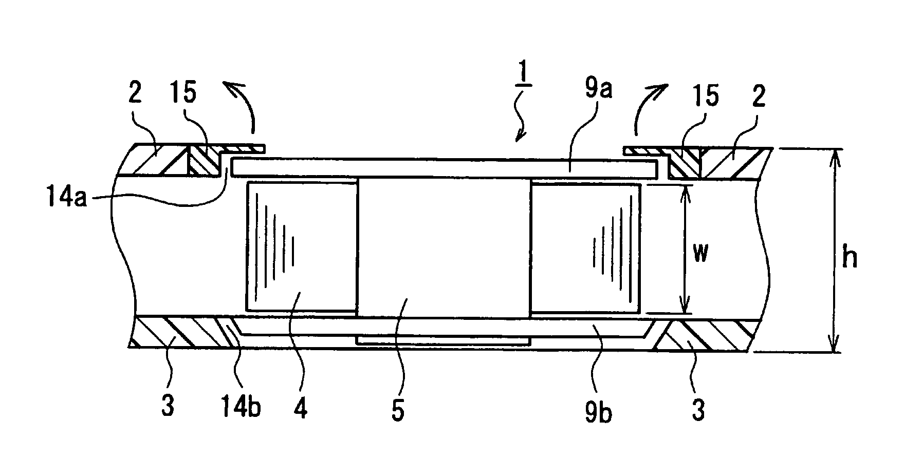
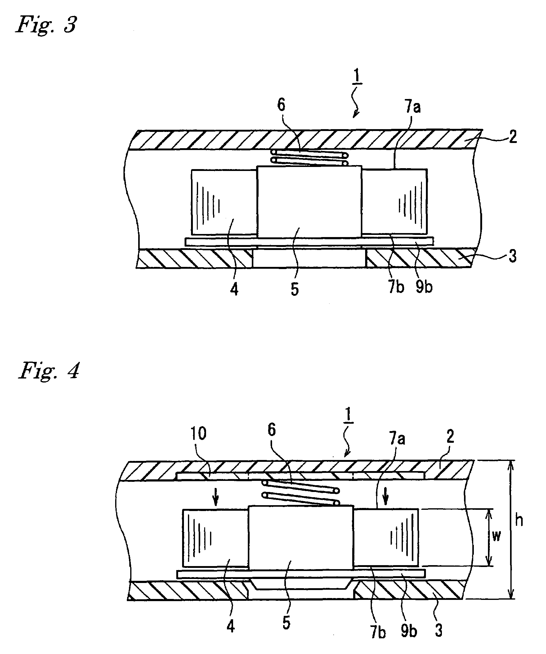
[0040]FIG. 3 is a fragmentary cross sectional view showing one example of the magnetic tape cartridge of the present invention. The present embodiment shares the same structure with the embodiment 1 except that the reel 5 has a lower flange 9b on the side of the winding surface 7b of the magnetic tape 4. Disposing the lower flange 9b allows damages on tape edges caused by contact between the magnetic tape 4 and the bottom shell 3 to be prevented.


PUM

PropertyMeasurementUnit
widthaaaaaaaaaa
thicknessaaaaaaaaaa
widthaaaaaaaaaa

Abstract

There is provided a magnetic tape cartridge, including a cartridge (1) composed of a top cartridge (2) and a bottom cartridge (3), a reel (5) rotatably disposed in the cartridge (1), and a magnetic tape (4) wound onto the reel (5), in which a width (w) of the magnetic tape (4) is over 12.65 mm, a thickness (h) of the cartridge (1) is 32 mm or less, and the width (w) of the magnetic tape is 60% to 90% of the thickness (h) of the cartridge (1).

Description

BACKGROUND OF THE INVENTION[0001]The present invention relates to a magnetic tape cartridge suitable for high-density recording.[0002]In recent years, means for high-speed information transmission such as optical fibers have attained considerable development, which makes it possible to transmit images and data sets containing enormous quantity of information, while at the same time, advanced technologies to record, reproduce and store these data sets are being required. Typical recording and reproducing media include flexible discs, magnetic drums, hard discs and magnetic tapes, and the magnetic tapes play a major role mainly as data backup medium since their recording capacity per reel is large. Today, with increase in the level of technology, the magnetic tapes are required to have higher recording capacity.[0003]The magnetic tapes are applied to various uses such as audio tapes, video tapes and computer tapes. In the field of data backup tapes in particular, with increased capaci...

Claims


Application Information

Patent Timeline
Patent Type & Authority Patents(United States)
IPC IPC(8): G11B23/107
CPCG11B23/043G11B23/107G11B23/044
Inventor SOGABE, TERUODOI, TSUGIHIRO
Owner HITACHT MAXELL LTD
Why Eureka
Try Eureka