Structure for mounting flat display module and method thereof

a technology for flat display modules and structures, applied in the direction of portable computer details, instruments, casings/cabinets/drawers of electric apparatus, etc., can solve the problems of cumbersome assembling process, poor exterior appearance, and increase the manufacturing cost of computers, so as to facilitate the installation of flat display modules, promote the convenience of personnel, and secure the appearance smooth and clear

Inactive Publication Date: 2006-02-21
LG ELECTRONICS INC
View PDF8 Cites 24 Cited by
  • Summary
  • Abstract
  • Description
  • Claims
  • Application Information

AI Technical Summary

Benefits of technology

[0011]An object of the present invention is to provide a structure and method for conveniently mounting a flat display module while securing a smooth and clear appearance of the display part.
[0012]An object of the present invention is to provide a structure for mounting a flat display module capable of further promoting the convenience of the personnel assembling the display part on which a flat display module is mounted through a more convenient procedure.
[0013]It is still another object of the present invention to provide a structure and method for mounting a flat display module capable of reducing manufacturing costs for a notebook computer.

Problems solved by technology

However, the screw(s) is / are exposed to the outside since these screws are inserted into the lateral side of the teat cover in the above-identified examples, thereby demonstrating a poor exterior appearance.
Further, the LCD module, the front module, and the rear cover are joined by a common screw hole, and the boss must therefore be exactly aligned to ensure a relatively difficult and cumbersome assembling process is completed properly.
Accordingly, manufacturing costs are increased for a computer such as a notebook computer having the above-identified structure of the background art.

Method used


Image

  • Structure for mounting flat display module and method thereof
  • Structure for mounting flat display module and method thereof
  • Structure for mounting flat display module and method thereof

Examples


first embodiment

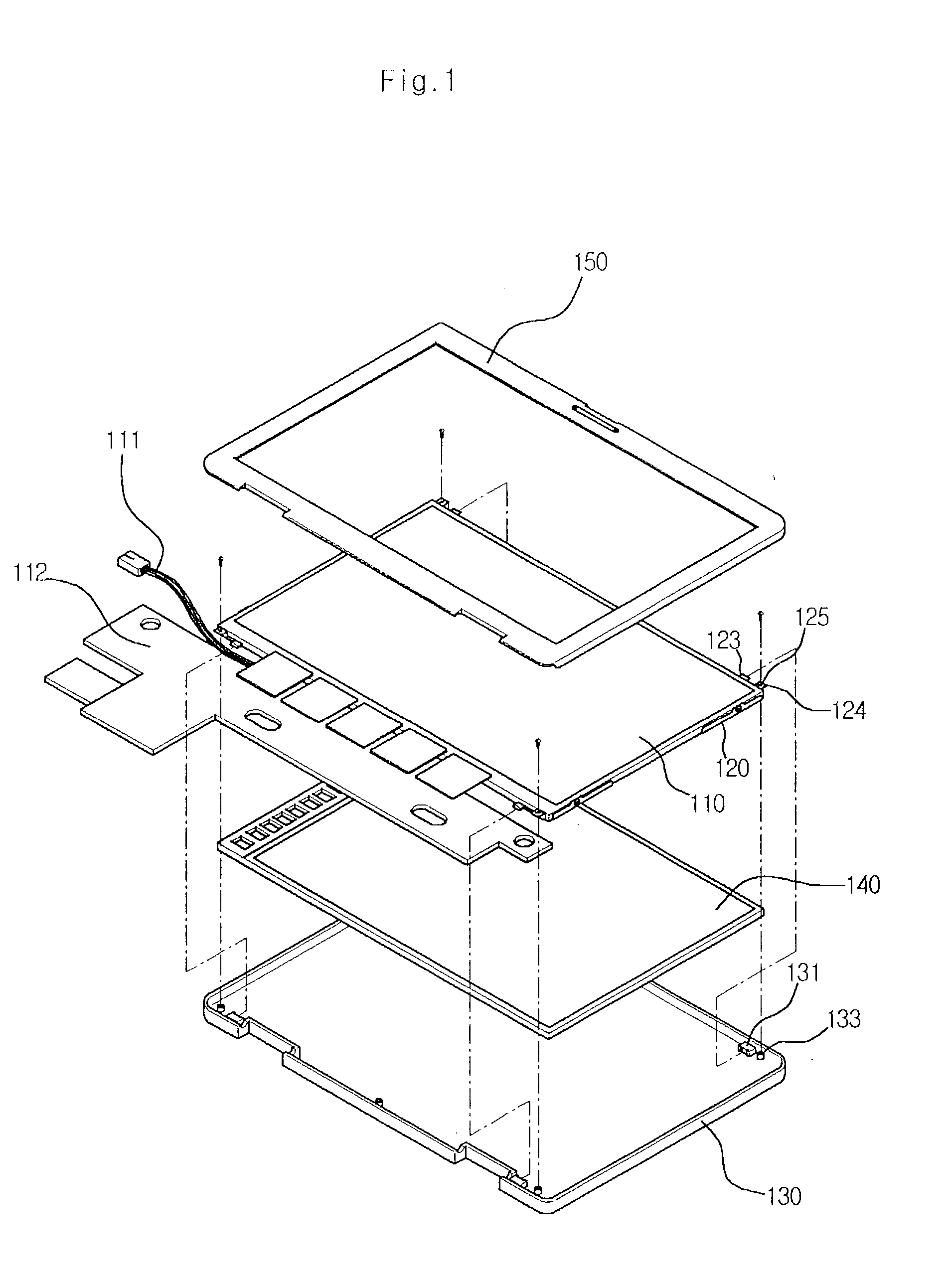
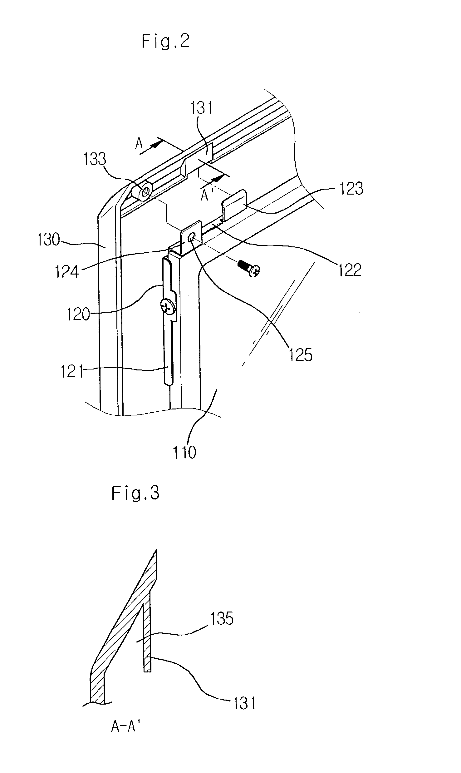
[0032]FIG. 1 is a perspective view of a structure for mounting a flat display module according to a first embodiment of the present invention. FIG. 2 is a partial, exploded perspective view detailing the construction and operation of the supporting member according to the first embodiment of the present invention. FIG. 3 is a cross-sectional view of a guiding block according to the first embodiment of the present invention. FIG. 4 is a perspective view of the supporting member according to the first embodiment of the present invention.

[0033]FIG. 1 is a perspective view of a structure for mounting the flat display module according to the first embodiment of the present invention, and FIG. 4 is a perspective view of the supporting member. The structure for mounting the flat display module according to the present invention includes a rear cover 130 for protecting the rear side of the display portion of the display module, a front cover 150 for protecting the front side of the display ...

second embodiment

[0043]FIG. 5 is a perspective view of a structure for mounting a flat display module according to a second embodiment of the present invention. FIG. 6 is a partial, perspective view of a hook-receiving member according to the second embodiment of the present invention. FIG. 7 is a partial, perspective view of a hook member according to the second embodiment of the present invention.

[0044]The second embodiment of the present invention is similar to the first embodiment in that the present embodiment includes a rear cover 230, a backlight panel 240, an LCD module 210, and a front cover 250. However, the supporting member and the related construction that have been suggested by the first embodiment (refer to FIG. 4) are not included.

[0045]Instead, an alternative structure for mounting the LCD module 210 conveniently and determining the positions of the front cover 250 and the rear cover 230 in a simple and exact manner is provided in the second embodiment. FIG. 5 is a perspective view ...

third embodiment

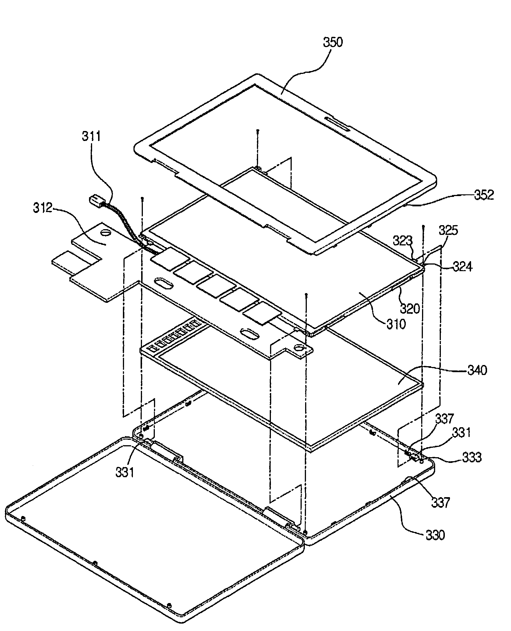
[0058]FIG. 8 is a perspective view of a structure for mounting a flat display module according to a third embodiment of the present invention. The third embodiment of the present invention is the same as the first and the second embodiments, and only differs in that constructions included in the first and the second embodiments are realized in a composite manner.

[0059]Accordingly, the construction relating to a rear cover 330, a front cover 350, a LCD module 310, a backlight panel 340, a supporting member 320, a joining hole 325, a joining part 324, a position guiding tab 323, a wiring 311, a substrate 312, a boss 333, a guiding block 331, a hook-receiving member 337, and a hook 351, is the same as the construction of the first and the second embodiments, and different in that these elements ate included in a combined embodiment.

[0060]As construction and operation suggested by the third embodiment is almost the same as the constructions by the first and the second embodiments, the d...


PUM

PropertyMeasurementUnit
structureaaaaaaaaaa
volumeaaaaaaaaaa
angleaaaaaaaaaa

Abstract

A structure for mounting a flat display module is described that includes a supporting member fixed on at least one edge portion of the flat display module and having a position guiding tab projecting to the exterior of the flat display module from one side. The structure includes a rear cover having a fitting groove in its edge portion corresponding to the position guiding tab for receiving the position guiding tab in order to provide a convenient and reliable method and structure for assembling a flat display module within a notebook computer.

Description

CROSS-REFERENCES TO RELATED APPLICATIONS[0001]This nonprovisional application claims priority under 35 U.S.C. §119(a) on Patent Applications Nos. 2002-18637 filed in Korea on Apr. 4, 2002, and 2002-18638 filed in Korea on Apr. 4, 2002, the entirety of each of which are herein incorporated by reference.BACKGROUND OF THE INVENTION[0002]1. Field of the Invention[0003]The present invention relates to a structure and method for mounting a flat display module, and more particularly to a structure and method for mounting a flat display module capable of conveniently and firmly mounting a liquid crystal display (LCD) module for use in a computer, e.g., a notebook computer. The present invention is capable of increasing process efficiency and reducing manufacturing costs by simplifying the production process of a notebook computer.[0004]2. Background of the Related Art[0005]A notebook computer is typically small in volume, lightweight and operates using a battery, so that a notebook computer...

Claims


Application Information

Patent Timeline
Patent Type & Authority Patents(United States)
IPC IPC(8): G06F1/16G02F1/13
CPCG02F1/133308G06F1/1616G06F1/1637G06F1/1683G02F2001/133322G02F2201/46Y10S345/905G02F2201/465G02F1/133322
Inventor HAN, KWANG KUKOH, WON SUB
Owner LG ELECTRONICS INC
Why Eureka
Try Eureka