Cutting tool

a cutting tool and cutting blade technology, applied in the field of cutting tools, can solve the problems of cutting the unwary consumer, difficult to open and protect plastic packaging, and becoming very sharp

Inactive Publication Date: 2006-02-28
PERLMUTTER THOMAS +1
View PDF3 Cites 27 Cited by
  • Summary
  • Abstract
  • Description
  • Claims
  • Application Information

AI Technical Summary

Benefits of technology

[0007]The invention incorporates a cutting blade with a housing and handle structure. The housing has a spring-biased blade. The spring-biased blade is extended into the cutting position. A small slit is cut into the heavy plastic wrap with the extended spring-biased blade. The end of the housing has an elongated finger portion for inserting into the slit created by the spring-biased blade so that the blade rests against the end of the slit. The blade is then urged forward extending the slit and opening the package.

Problems solved by technology

The plastic packaging is very difficult to open safely.
The heavy plastic resists cutting, but can become very sharp and cut the unwary consumer.

Method used


Image

  • Cutting tool
  • Cutting tool
  • Cutting tool

Examples


Embodiment Construction

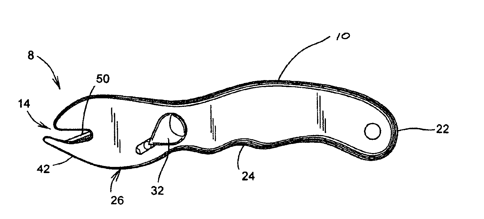
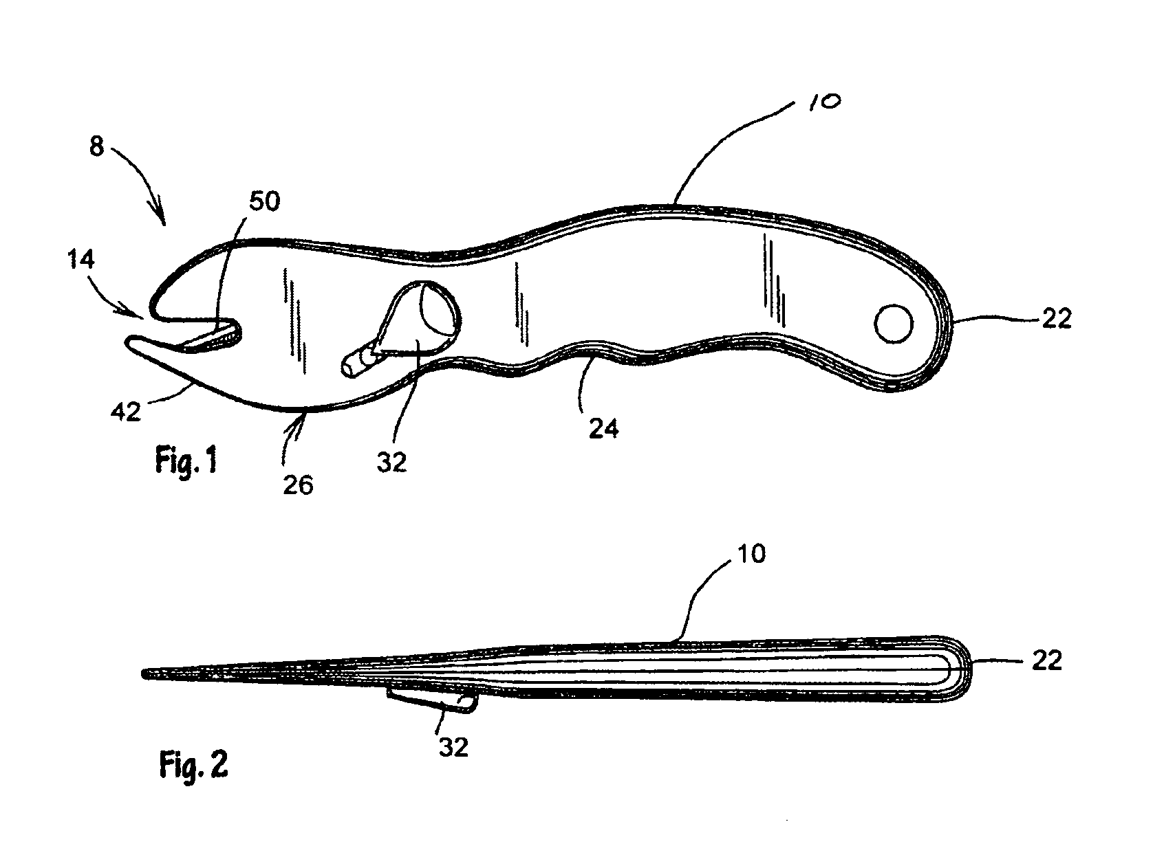
[0014]A cutting tool 8 is shown in FIGS. 1-4. It includes a housing 10 having a first end 14 with a first edge 18 and a second end 22. A handle 24 extends from the second end 22 of the housing 10.

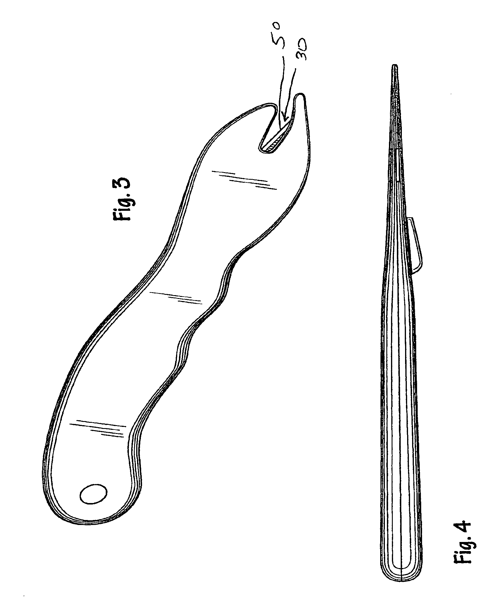
[0015]It also includes a first blade 26 with a cutting position 30 and a retracted position inside the housing 10. A relocation implement 32 moves the first blade 26 from the retracted position to the cutting position 30.

[0016]An elongated finger portion 42 extends from the first end 14 of the housing 10 forming a cantilever. The finger portion 42 runs opposite the first edge 18 of the first end 14. The finger portion 42 and the first edge 18 define an elongated opening having a juncture end 46 at the first end 14 of the housing 10.

[0017]A second blade 50 is embedded at the juncture end 46. The second blade 50 is shaped, sized and orientated to facilitate forward slitting of heavy plastic sheet.

[0018]The relocation implement 32 includes a thumb tab 54, a track and a biasing means. The first...


PUM

PropertyMeasurementUnit
structuresaaaaaaaaaa
obtuse angleaaaaaaaaaa

Abstract

A cutting tool includes a housing having a first end with a first edge and a second end. A handle extends from the second end of the housing. The housing has a slideable blade with a cutting position and a retracted position inside the housing. A finger portion is cantilevered from the first end of the housing. The finger portion and the first edge define an elongated opening having a juncture end at the first end of the housing. A cutting edge is embedded at the juncture end. The cutting edge is shaped, sized and orientated to facilitate forward slitting of heavy plastic sheet. The slideable blade slides axially along a track. A biasing means repositions the slideable blade from the cutting position to the retracted position.

Description

CROSS-REFERENCE TO RELATED APPLICATIONS[0001]U.S. Design Patent ApplicationSTATEMENT REGARDING FEDERALLY SPONSORED RESEARCH OR DEVELOPMENT[0002]Not ApplicableREFERENCE TO MICROFICHE APPENDIX[0003]Not ApplicableFIELD OF INVENTION[0004]The present invention relates generally to cutting tools and more particularly to a knife for cutting heavy plastic.BACKGROUND OF THE INVENTION[0005]Product packaging has undergone substantial change in recent years. The packaging must withstand the rigors of shipping, impede shop-lifters, and attractively display the product for retail sales and hold the product in a compact container. Increasingly, the packaging material of choice has become plastic. The plastic is formed from heavy clear sheet to conform to the contours of the products and to display the products for the retail sales. The plastic packaging is very difficult to open safely. The heavy plastic resists cutting, but can become very sharp and cut the unwary consumer.[0006]There is a clear ...

Claims


Application Information

Patent Timeline
Patent Type & Authority Patents(United States)
IPC IPC(8): B26B1/08B26B3/00B26B27/00B65B69/00
CPCB26B1/08B65B69/0033B26B27/005Y10T83/04Y10T83/0524
Inventor PERLMUTTER, THOMASLEWIS, ROBERT L.
Owner PERLMUTTER THOMAS
Why Eureka
Try Eureka