Ski boot and ski boot binding

a technology of ski boot and ski boot, which is applied in the field of ski equipment, can solve the problems of phantom foot injury, increased knee load of ski boot, and downward force of ski tail, so as to increase the inside turn ski edge angle, increase the top of the ski, and increase the edge holding force

Inactive Publication Date: 2006-02-28
WULF ELMER B +1
View PDF18 Cites 6 Cited by
  • Summary
  • Abstract
  • Description
  • Claims
  • Application Information

AI Technical Summary

Benefits of technology

[0010]The steering system of this invention is configured to provide lateral movement or “flexing” of the boot relative to the binding when the skier applies pressure with both forward and lateral components (force vectors) to the front cuff. As such, the steering system is able to increase the inside turn ski edge angle simply by applying the appropriate forward pressure while turning the skis, and provides a skier with more edge holding force in a steep racing-type turn because the skier's weight is more on top of the skis. In accordance with a preferred aspect o the invention, the steering system comprises a tracking assembly located between the front cuff and the foot shell of the boot. A particular tracking assembly comprises a follower engaged with a track member having at least two tracks that diverge from each other in the lateral directions of the boot. In this configuration, the follower can be caused to track along a fi...

Problems solved by technology

For ski boots of the clam shell-type (having front and rear cuffs pivotably coupled to a foot shell), this stiffness is the result of permitting only limited lean adjustment in the forward direction and essentially none in the rearward direction.
While protecting the ankle, boot stiffness places greater loads on the knee, such that sprains and tears of the anterior cruciate ligament (ACL) are now a relatively common type of injury associated ...

Method used


Image

  • Ski boot and ski boot binding
  • Ski boot and ski boot binding
  • Ski boot and ski boot binding

Examples


Embodiment Construction

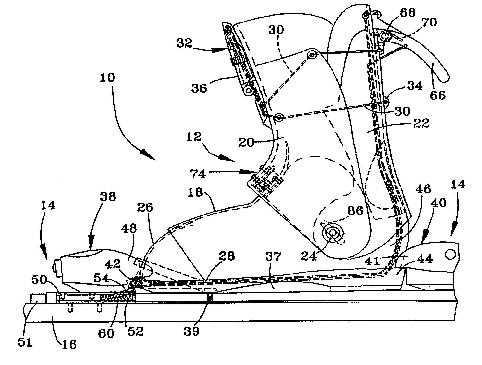
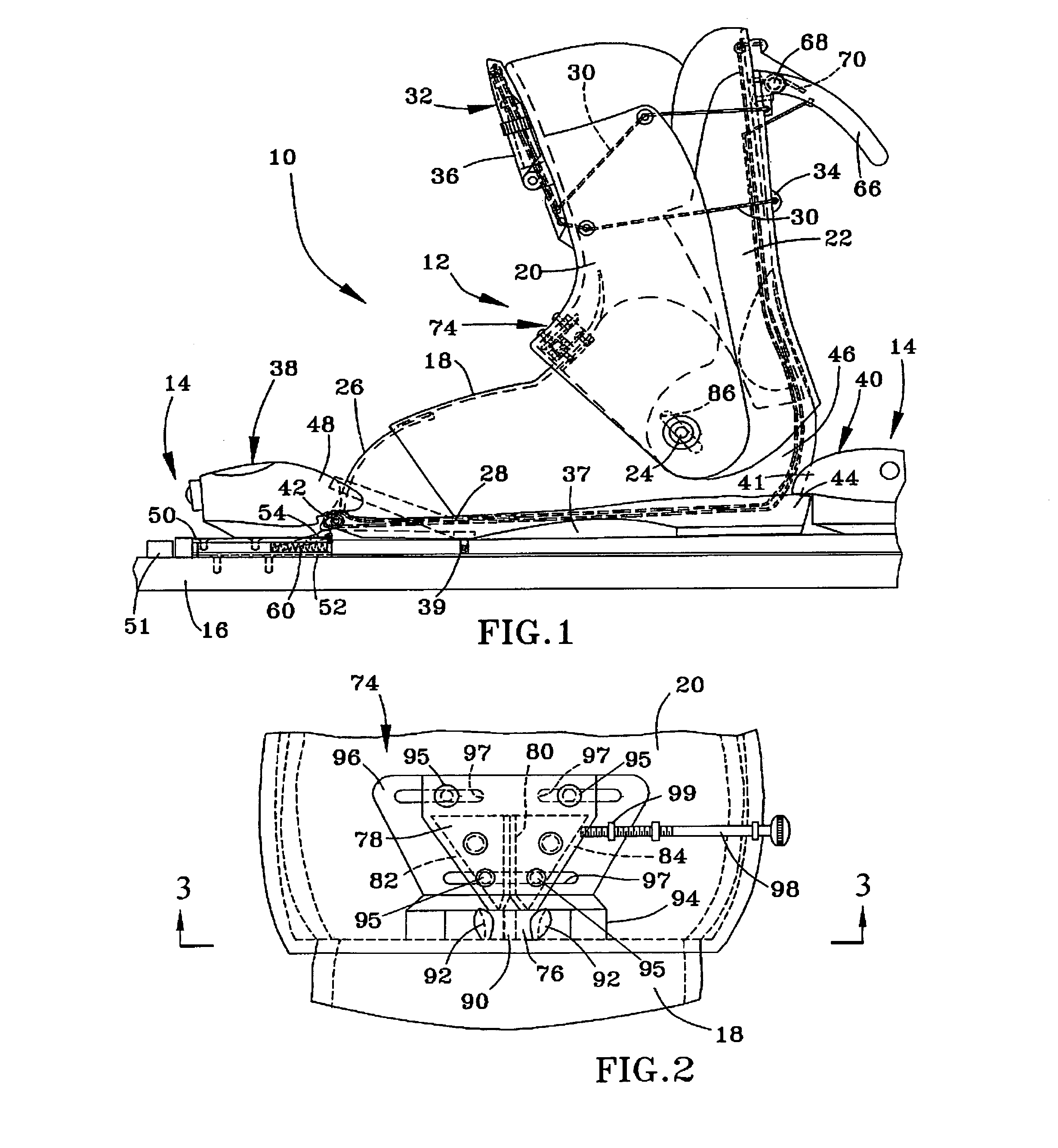
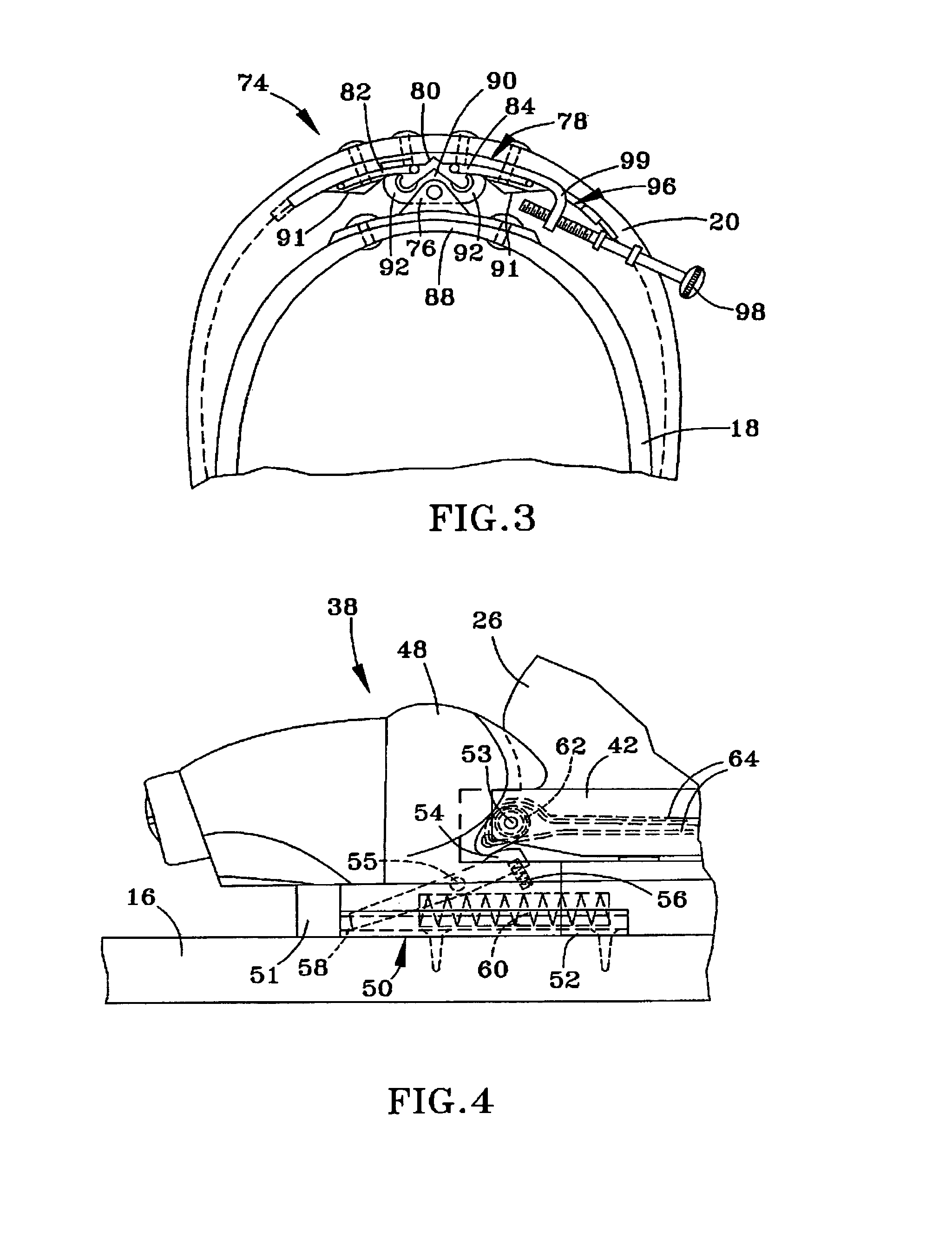
[0017]A ski boot and binding assembly 10 in accordance with a first embodiment of the invention is Illustrated in FIGS. 1 through 4, with alternative embodiments of the invention being illustrated in FIGS. 5 and 6. As will become apparent from the following discussion, the embodiments are depicted as combining two features of this invention—a toe release system and a steering system—though each of these features could be utilized separately from the other.

[0018]With reference to FIGS. 1 through 4, the ski boot and binding assembly 10 comprises a ski boot 12 mounted to a binding assembly 14, the latter of which is secured to a ski 16. The boot 12 is represented as being of the clam shell-type, and as such has a foot shell 18 and front and rear cuffs 20 and 22. The cuffs 20 and 22 are pivotably attached to each other and to the foot shell 18 at two pivot points defined by hinges 24 located on opposite sides of the boot 12. The rearward edge of the front cuff 20 overlies the rear cuff ...


PUM


Abstract

Ski equipment that provides, preferably in combination, a toe release system for reducing the risk of knee injuries and a steering system for increasing turn performance. In the toe release system, the binding has a toe binding portion secured with a securing element at a forward position relative to a rear binding portion of the binding, and a release element that communicates with the securing element for releasing the toe binding portion in response to the application of pressure to the rear cuff of a boot secured with the binding, permitting movement of the toe binding portion away from the rear binding portion and thereby releasing a toe of the boot. In the steering system, the boot includes a tracking assembly that permits controlled flexing of the front and rear cuffs of the boot by applying forward and lateral pressure to the front cuff.

Description

CROSS REFERENCE TO RELATED APPLICATIONS[0001]This application claims the benefit of U.S. Provisional No. 60 / 382,499, filed May 22, 2002.BACKGROUND OF INVENTION[0002]1. Field of the Invention[0003]The present invention generally relates to ski equipment. More particularly, this invention relates to a ski boot and ski boot binding system that provides, preferably in combination, a toe release system for reducing the risk of knee injuries and an ankle-flex steering system for increasing turn performance.[0004]2. Description of the Related Art[0005]The stiffness of modern ski boots has drastically reduced the incidence of ankle injuries. For ski boots of the clam shell-type (having front and rear cuffs pivotably coupled to a foot shell), this stiffness is the result of permitting only limited lean adjustment in the forward direction and essentially none in the rearward direction. While protecting the ankle, boot stiffness places greater loads on the knee, such that sprains and tears of ...

Claims


Application Information

Patent Timeline
IPC IPC(8): A63C9/086A63C9/00A63C9/085A63C9/088
CPCA63C9/001A63C9/088A63C9/08564A63C9/08578A63C9/08542A63C7/1013
Inventor WULF, ELMER B.WULF, MARK E.
Owner WULF ELMER B
Why Eureka
Try Eureka