

Golf ball
a golf ball and ball technology, applied in the field of golf balls, can solve the problems of adversely affecting the durability of repeated impact, and achieve the effects of short flight distance, exacerbated and reduced durability to cracking by repeated impa
Inactive Publication Date: 2006-03-07
BRIDGESTONE SPORTS
View PDF14 Cites 6 Cited by
- Summary
- Abstract
- Description
- Claims
- Application Information
AI Technical Summary
Benefits of technology
[0105]In the resin composition comprising components (a) and (b) as essential components, various additives may be blended in addition to the resin components, if necessary. Such additives include, for example, pigments, dispersants, antioxidants, UV absorbers, UV stabilizers, parting agents, plasticizers, and inorganic fillers (zinc oxide, barium sulfate, titanium dioxide, etc.). It is preferred that components (a) and (b) be included in a total amount of at least 30% by weight, especially 60 to 100% by weight in the resin composition in order to achieve the desired effects of the invention.
[0106]It is noted that the cover outer layer formed using the resin composition has a Shore D hardness of at least 55, preferably at least 57, and more preferably at least 59. If the Shore D hardness of the cover is too low, rebound becomes poor, with short flight distance. Also, the cover outer layer has a Shore D hardness of up to 65, preferably up to 63, and more preferably up to 61. If the Shore D hardness of the cover is too high, durability to cracking by repeated impact may be exacerbated. It is noted that the Shore D hardness of the cover is a measurement by a type D durometer according to ASTM D2240.
[0107]Also, with respect to the gage of the cover outer layer, the upper limit is 1.4 mm, preferably 1.3 mm and more preferably 1.2 mm. Beyond the upper limit, the spin rate of the ball when hit with a driver (W#1) may not be suppressed, failing to travel a distance. The lower limit of the cover gage is 0.5 mm, preferably 0.9 mm, and more preferably 1.1 mm. Below the lower limit, durability to cracking by repeated impact may be exacerbated.
[0108]In the practice of the invention, the cover resin composition for the cover outer layer should have a melt flow rate of at least 3, preferably at least 4, more preferably at least 4.5, as measured according to JIS K7210 (1999). If the melt flow rate of the cover resin composition is below the lower limit, the permeation of molten resin through the mold cavity during injection molding may be impeded, resulting in molding defects. It is noted that the measurement according to JIS K7210 (1999) indicates a melt flow rate of the cover resin composition as measured under conditions: test temperature 190° C. and test load 21.2 N (2.16 kgf).
[0109]The total gage of the cover is generally in a range of 1.5 to 3.0 mm, preferably 2.0 to 2.8 mm, more preferably 2.4 to 2.6 mm. If the total gage of the cover is too thin, durability to cracking by repeated impact may be exacerbated. If the total gage of the cover is too thick, the spin rate on driver (W#1) shots may increase, sometimes failing to travel a distance.
[0110]According to the invention, the hardness of the cover outer layer is set higher than that of the cover inner layer. The hardness difference between the cover outer layer and the cover inner layer is preferably at least 1, more preferably at least 3, even more preferably at least 5 Shore D hardness units. With too small a hardness difference, the feel on impact may be exacerbated and the spin rate on driver (W#1) shots may increase, failing to travel a distance. The upper limit of hardness difference is preferably up to 25, more preferably up to 20, even more preferably up to 15. With too large a hardness difference, durability to cracking by repeated impact may be exacerbated.
Problems solved by technology
In the event the ball structure is a two-layer structure consisting of a core and a single layer cover, since support pins are used for holding the core during injection molding, interfaces reaching the core are formed in the wake of support pins, adversely affecting durability to repeated impact.
Method used
View moreImage
Smart ImageViewing Examples

Examples
example
[0113]Examples and Comparative Examples are shown below for illustrating the invention, but the invention is not limited to the Examples.
Login to View More PUM
 Abstract
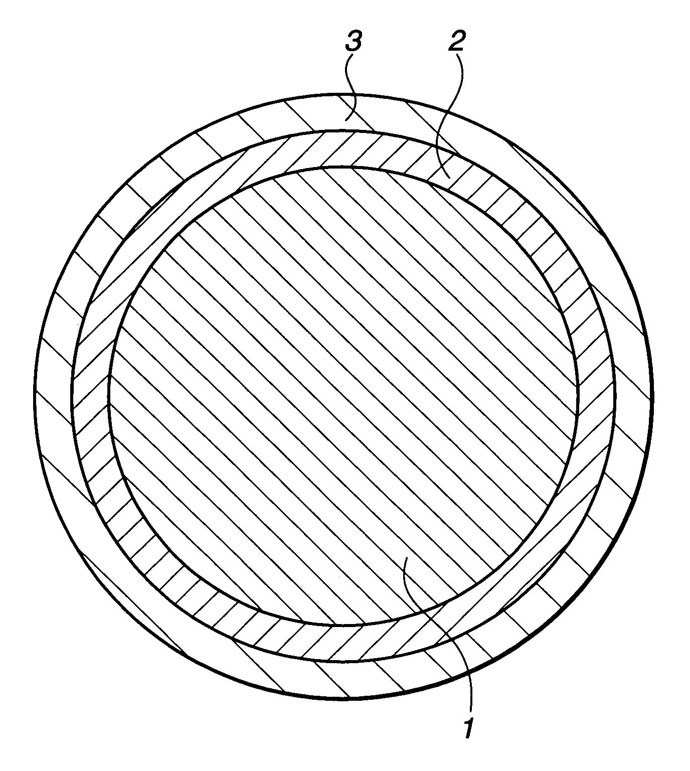
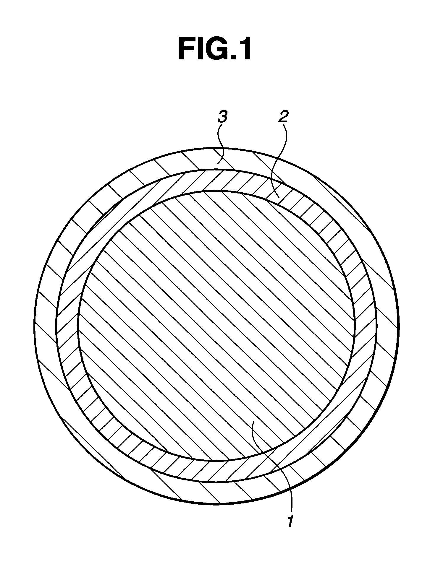
A golf ball comprising a core and a multilayer cover including at least a cover inner layer and a cover outer layer is characterized in that the core has a hardness corresponding to a compressive deflection amount of at least 3.5 mm when the load applied thereto is increased from an initial load of 10 kgf to a final load of 130 kgf, the cover outer layer is made of a resin composition having organic short fibers incorporated therein, the resin composition has a melt flow rate of at least 3 as measured according to JIS K7210, the cover outer layer has a Shore D hardness of at least 55 and is harder than the cover inner layer, and the cover outer layer has a gage of up to 1.4 mm. The golf ball has a soft feel, offers superior flight performance to even those golf players with a low head speed of 35 m / s or less, and is improved in durability to repeated impact and moldability.
Description
BACKGROUND OF THE INVENTION[0001]This invention relates to a golf ball having a soft feel on impact, which offers superior flight performance to even those golf players who swing a driver (W#1) at a low head speed (HS) of 35 m / s or less, and is improved in durability to repeated impact and moldability.[0002]In order for the golf ball to present a soft feel on impact, the core must be made relatively soft. Development works on golf balls have been made not only for high head speeds, but also for low head speeds. For the prior art golf balls intended for low head speeds, a soft feel was obtained at the sacrifice of travel distance. It was difficult to find a good compromise between travel distance and feel.[0003]More specifically, low head speed golf players, who wish to increase the travel distance, tend to use a driver (W#1) having a larger loft angle than high head speed golf players. In this situation, when the ball is hit, the ball launches at a larger angle and receives more spi...
Claims
Login to View More Application Information
Patent Timeline
 Patent Type & Authority Patents(United States)
IPC IPC(8): A63B37/12A63B37/00A63B37/06
CPCA63B37/0003A63B37/0024A63B37/0031A63B37/0033A63B37/0036A63B37/0092A63B37/0046A63B37/0062A63B37/0065A63B37/0075A63B37/0043
Inventor WATANABE, HIDEONAGASAWA, HIROYUKI
Owner BRIDGESTONE SPORTS