
Method for adjusting digital images to compensate for defects on film material

a technology of digital images and film material, applied in the direction of color television, electrical equipment, television systems, etc., can solve the problem that the threshold may not always be sufficient to distinguish defects from picture material

Inactive Publication Date: 2006-03-14
PANDORA INT
View PDF22 Cites 23 Cited by
  • Summary
  • Abstract
  • Description
  • Claims
  • Application Information

AI Technical Summary

Benefits of technology

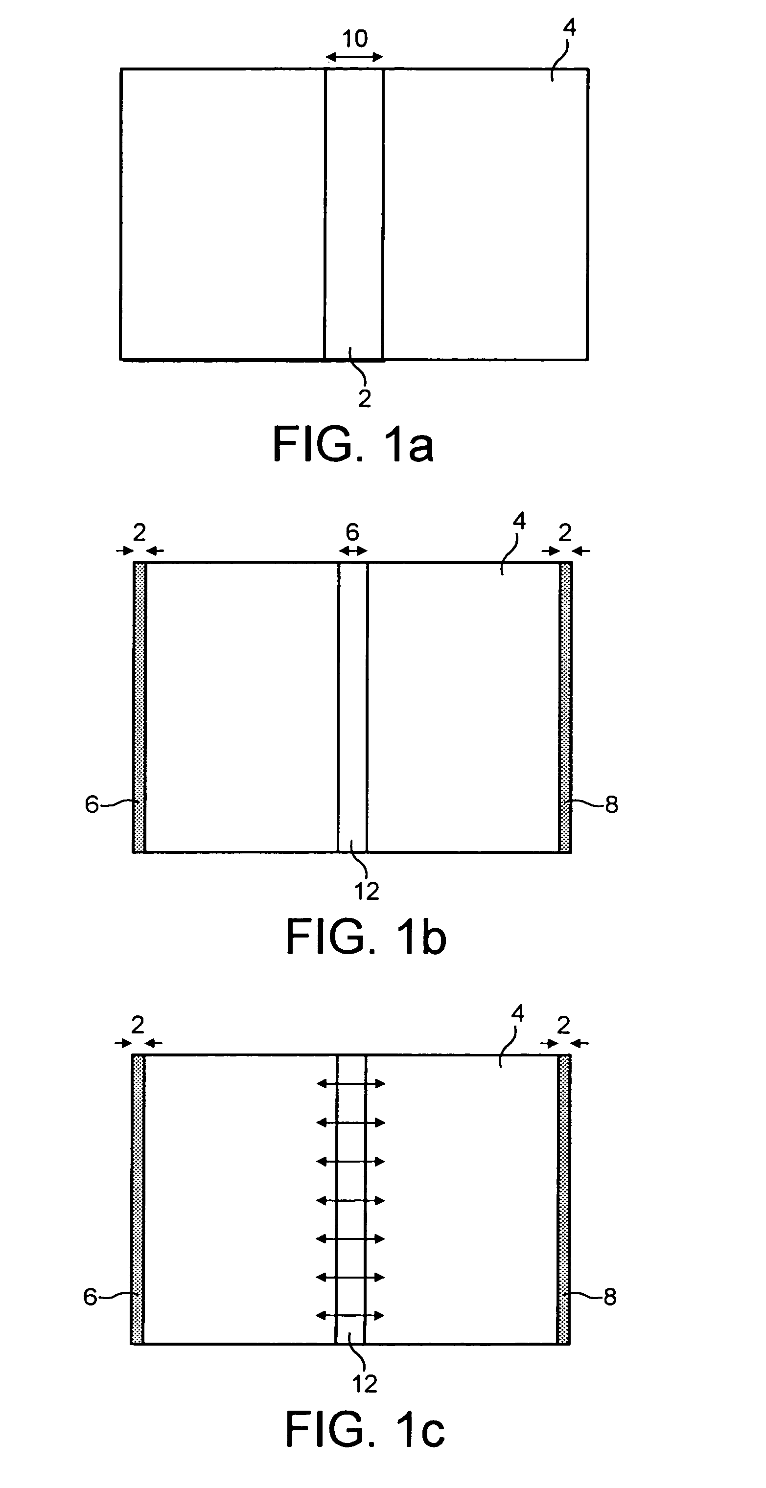
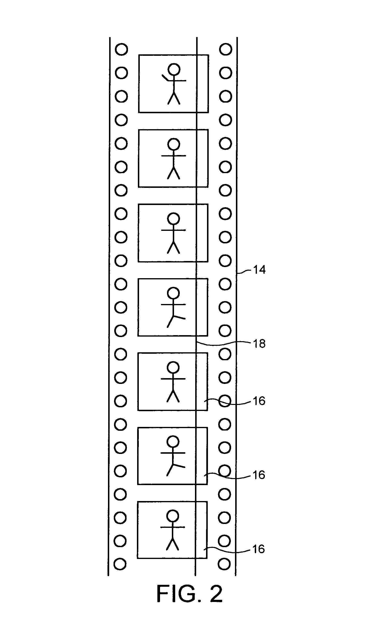
[0013]The detection of defects may be carried out solely using the steps outlined above, with entire frames being analysed for pixels beyond the threshold. Alternatively, and particularly in the case of scratches, there may be a preliminary manual step to identify one or more pixels in a scratch. An operator could for example position a cursor on a scratch on a viewing monitor. The method of the invention will then be used to identify the remaining pixels corresponding to the scratch by looking only in a column of a chosen width in the frame concerned, and in subsequent frames, on the basis that the scratch will extend generally in the direction of film transport. This will reduce time as it will not be necessary to analyse each pixel in each frame. Where an operator discerns that there are relatively few scratches on a film, this may be the most efficient way of proceeding. If there are many scratches then it may be better to analyse all pixels and to perform the operation completely automatically.
[0019]Thus, in accordance with this invention there is provided a method of correcting for flicker in digital images obtained by scanning frames of cinematographic film, comprising the steps of: identifying frames in which flicker is present; identifying relatively bright regions in those frames whose brightness is above a predetermined level, and correcting digital pixels in those relatively bright regions so as to compensate for the effect of flicker.

Problems solved by technology

Such thresholds may not always be sufficient to distinguish defects from picture material.

Method used


Image

  • Method for adjusting digital images to compensate for defects on film material
  • Method for adjusting digital images to compensate for defects on film material
  • Method for adjusting digital images to compensate for defects on film material

Examples


Embodiment Construction

[0028]In a first embodiment of the invention, an operator manually enters the position of a pixel in a scratch on one frame. To do this, the operator will have positioned the cursor on a scratched pixel.

[0029]The pixel values are analysed under the assumption that ‘white’ scratches will have (in an 8 bit quantisation) values above a maximum threshold. This threshold can be varied, but typically will be value 245. Similarly, ‘black’ scratches will be below a variable minimum threshold. This threshold will typically be 10. Thus firstly, the user determines the mode of material that he wishes to scratch correct from positive or negative, which then chooses which threshold is used for scratch detection.

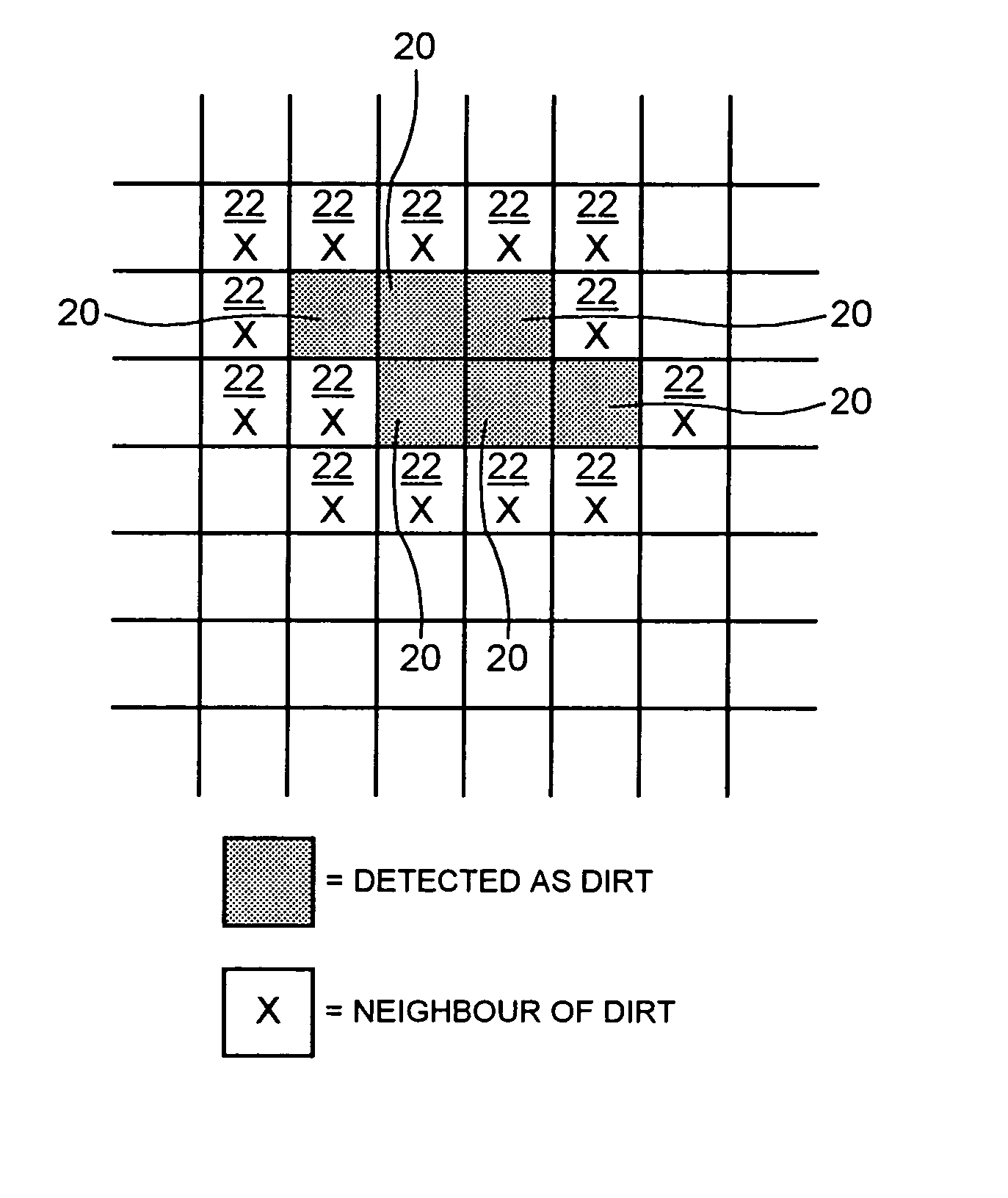
[0030]Scratches usually will contain continuous positional information. Thus a scratched pixel is highly likely to have another scratched pixel next to it. A two stage identification for scratches is therefore provided. It is possible to look at the neighbours of the manually identified s...


PUM


Abstract

A method of scanning frames of cinematographic film to generate digital values of pixels constituting images on the film frames is provided in which pixels corresponding to defects on the film are identified and the values of such pixels are adjusted to compensate for the defects, the identification of the pixels corresponding to defects on the film being carried out by identifying pixels whose value is beyond a predetermined threshold.A method of correcting for flicker in digital images obtained by scanning cinematographic film is also provided. This method comprises the steps of identifying frames in which flicker is present; identifying relatively bright regions in those frames whose brightness is above a predetermined level, and correcting digital pixels in those relatively bright regions so as to compensate for the effect of flicker.

Description

INTRODUCTION[0001]The present invention relates to the conversion of images stored on cinematographic film to corresponding electrical signals. More particularly, the invention relates to methods of modifying the electrical signals so as to compensate for degradation of the cinematographic film.[0002]Cinematographic film has now been in existence for over one hundred years. There is a wealth of history and entertainment in existence on this medium, in nearly every country in the world. However, photographic film degrades with age. Thus, there is a need for methods to counteract damage done to the film by the passage of time, damage caused by bad storage or careless handling, and so forth.BRIEF DESCRIPTION OF THE PRIOR ART[0003]Methods of correcting for fading in film are known in the art. For example, U.S. Pat. No. 5,212,518 in the name of Yamatoya & Co., Ltd. describes a method in which the unfaded values of pixels in a digital image obtained from film are estimated by assuming a l...

Claims


Application Information

Patent Timeline
Patent Type & Authority Patents(United States)
IPC IPC(8): H04N9/47H04N5/253H04N9/64
CPCH04N5/253
Inventor ZELL, JOACHIM
Owner PANDORA INT
Learn More