Strainer

a technology of strainer and discharge tube, which is applied in the direction of water installations, washstands, constructions, etc., can solve the problems of clogging the discharge tube, affecting the discharge of water, and splashing of the floor and sink counter

Inactive Publication Date: 2006-03-21
LIN KUN HSI
View PDF64 Cites 72 Cited by
  • Summary
  • Abstract
  • Description
  • Claims
  • Application Information

AI Technical Summary

Benefits of technology

[0004]In view of the aforesaid disadvantages, the primary object of the present invention is to provide a strainer with a button in the center of a filter that is depressible to control water collection or discharge.

Problems solved by technology

As a result, the floor and sink counter often are splashed with water, and a portion of the residues could drop into the discharge tube with the water and accumulate and clog the discharge tube after a period of time.

Method used


Image

  • Strainer
  • Strainer
  • Strainer

Examples


Embodiment Construction

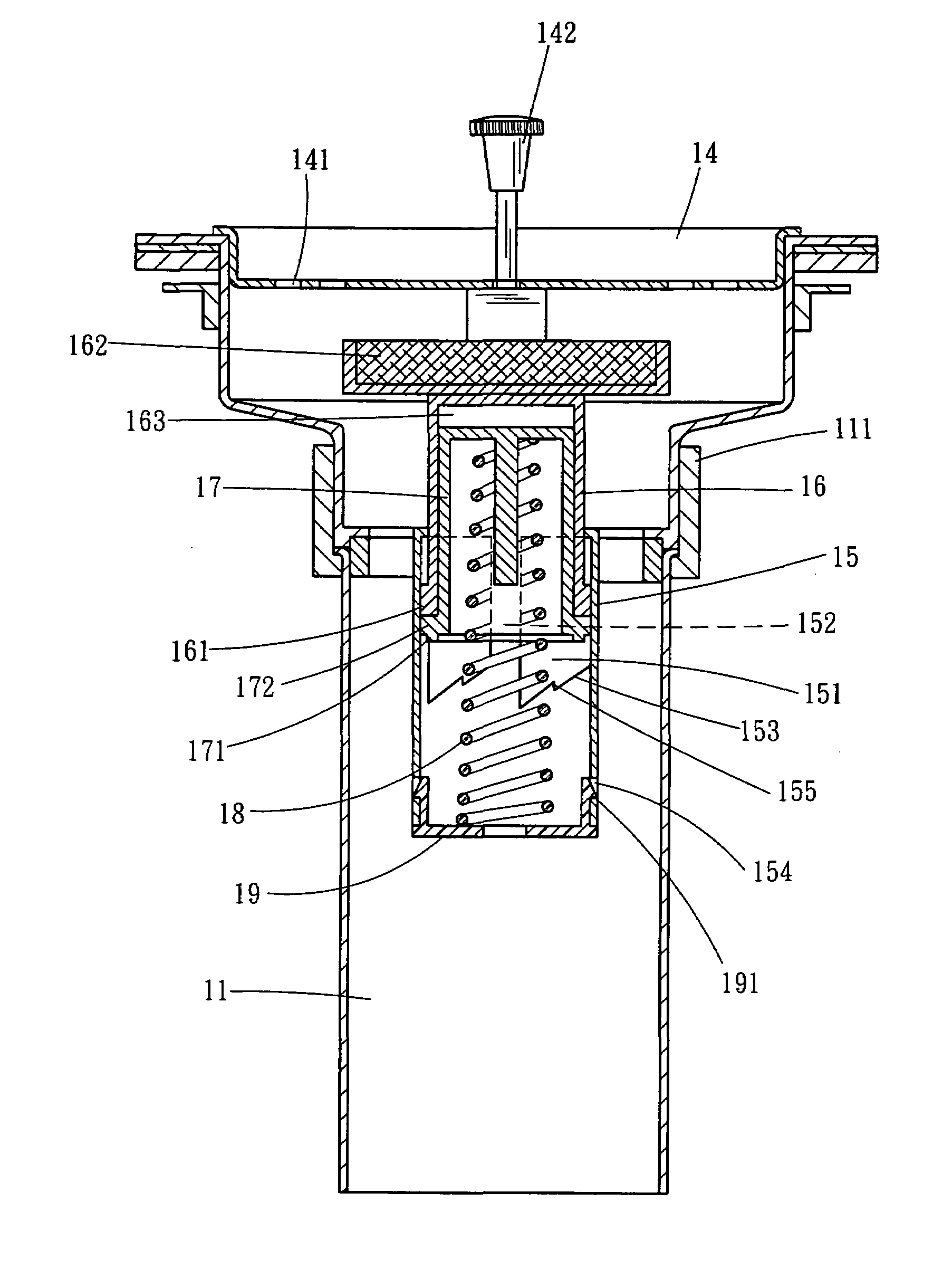
[0014]Please refer to FIGS. 3 and 4, the strainer 10 according to the present invention includes a trumpet shape body with screw threads on the bottom to couple with a screw sleeve 111 of a duct 11, and a water collector 12 on a upper side that has a round opening directing upwards. The water collector 12 has a drain port 13 on the bottom.

[0015]A filter 14 is provided which is formed like a tray with a perimeter mating the water collector 12. The filter 14 has a plurality of drain apertures 141 on the bottom and a button 142 formed in a strut running through the center thereof.

[0016]Refer to FIG. 5A, a hollow tube 15 is coupled on the bottom of the water collector 12 and housed in the duct 11. The tube 15 has four bulged and longitudinal walls 151 on the inner perimeter that are spaced from one another to form a flute 152 between every two neighboring bulged walls 151. The bulged wall 151 further has an arched guiding section 153 on the bottom. The guiding section 153 has an indente...


PUM


Abstract

A strainer includes a water collector on an upper side, and a tube coupled on the bottom of the water collector. The tube has flutes formed on the inner wall. An extendable rod is housed in the tube and has lugs on the periphery to slide in the flutes. A latch member is housed in a housing chamber on the bottom of the extendable rod and has coupling sections formed on the bottom in an annular manner. An elastic element has a top end housed in the latch member and a bottom end fastened to a coupling member to couple on the bottom end of the tube. The top end of the extendable rod is fastened to a plug which is insertable in the drain port of the water collector. A filter is located in the water collector and has a button in the center depressible up and down to control water collection or discharge.

Description

FIELD OF THE INVENTION[0001]The present invention relates to a strainer and particularly to a sink strainer having a button in the center of a filter that is depressible to control water collection and discharge.BACKGROUND OF THE INVENTION[0002]A conventional strainer for kitchen sinks (referring to FIGS. 1 and 2) generally includes a hollow barrel 1 which has a funnel shape opening 2 with a larger diameter at the upper side and a smaller diameter at the lower side. The barrel 1 has an outer wall screwed on the bottom of the sink and a plurality of apertures 3 formed on the bottom thereof leading to a discharge tube beneath the sink. The barrel 1 has a rectangular anchor bore 4 in the center of the bottom. A disk type filter 5 made of metal is provided with filter holes 6 formed on the bottom and peripheral wall. There is a handle 7 located on the top of the center of the filter 5. The bottom of the filter 5 is coupled with a plug 8 made of rubber to stop water flow. The plug 8 has ...

Claims


Application Information

Patent Timeline
Patent Type & Authority Patents(United States)
IPC IPC(8): A47K1/14E03C1/26
CPCE03C1/262
Inventor LIN, KUN-HSI
Owner LIN KUN HSI
Why Eureka
Try Eureka