Explosively actuated tools

Active Publication Date: 2006-03-21
ILLINOIS TOOL WORKS INC
View PDF9 Cites 32 Cited by
  • Summary
  • Abstract
  • Description
  • Claims
  • Application Information

AI Technical Summary

Benefits of technology

[0011]In a practical embodiment of the invention, the said structure includes a coupling to which the pole-like handle is attached and the coupling is slidably mounted within an enclosure at the rear end of the tool housing, with the ball being located in a space defined between the coupling and a rear face of the enclosure such that in a firing-inhibiting position of the ball, the ball will lie against said rear face to prevent forwards displacement of the coupling to a position adjacent said rear face at which firing would otherwise be enabled, a forward face of the coupling providing a chamber into which the ball can move at predetermined orientations of the tool to thereby permit the coupling to move into the position adjacent said rear face and at which firing is enabled.

Problems solved by technology

Although the safety device is able to properly function to prevent firing in that orientation it is not designed to function to prevent the tool from being fired when in a substantially horizontal orientation or even in an orientation just below the horizontal.

Method used


Image

  • Explosively actuated tools
  • Explosively actuated tools
  • Explosively actuated tools

Examples


Embodiment Construction

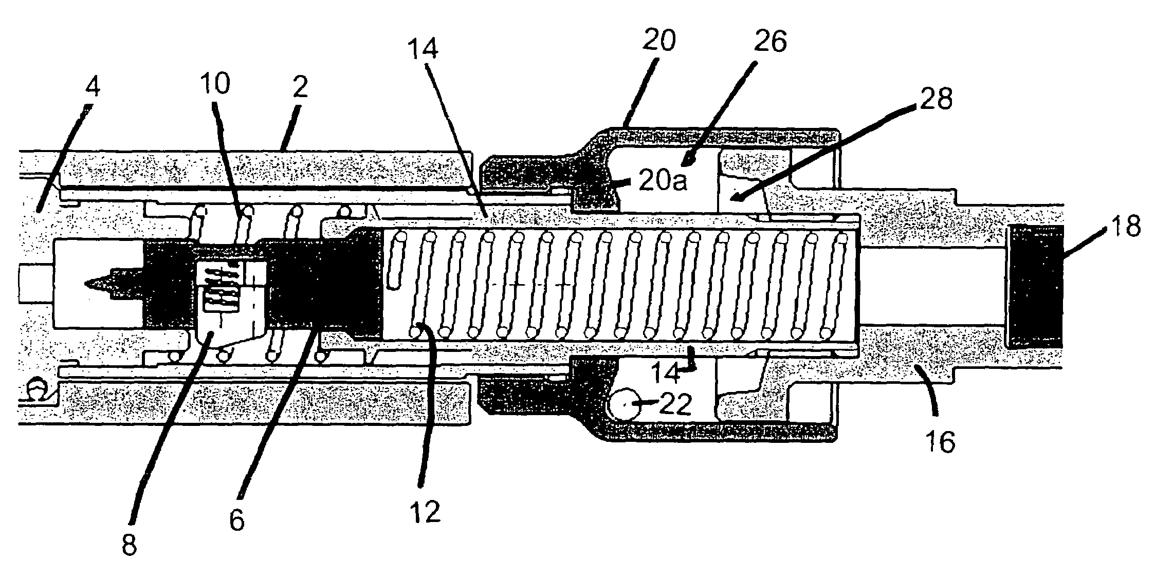
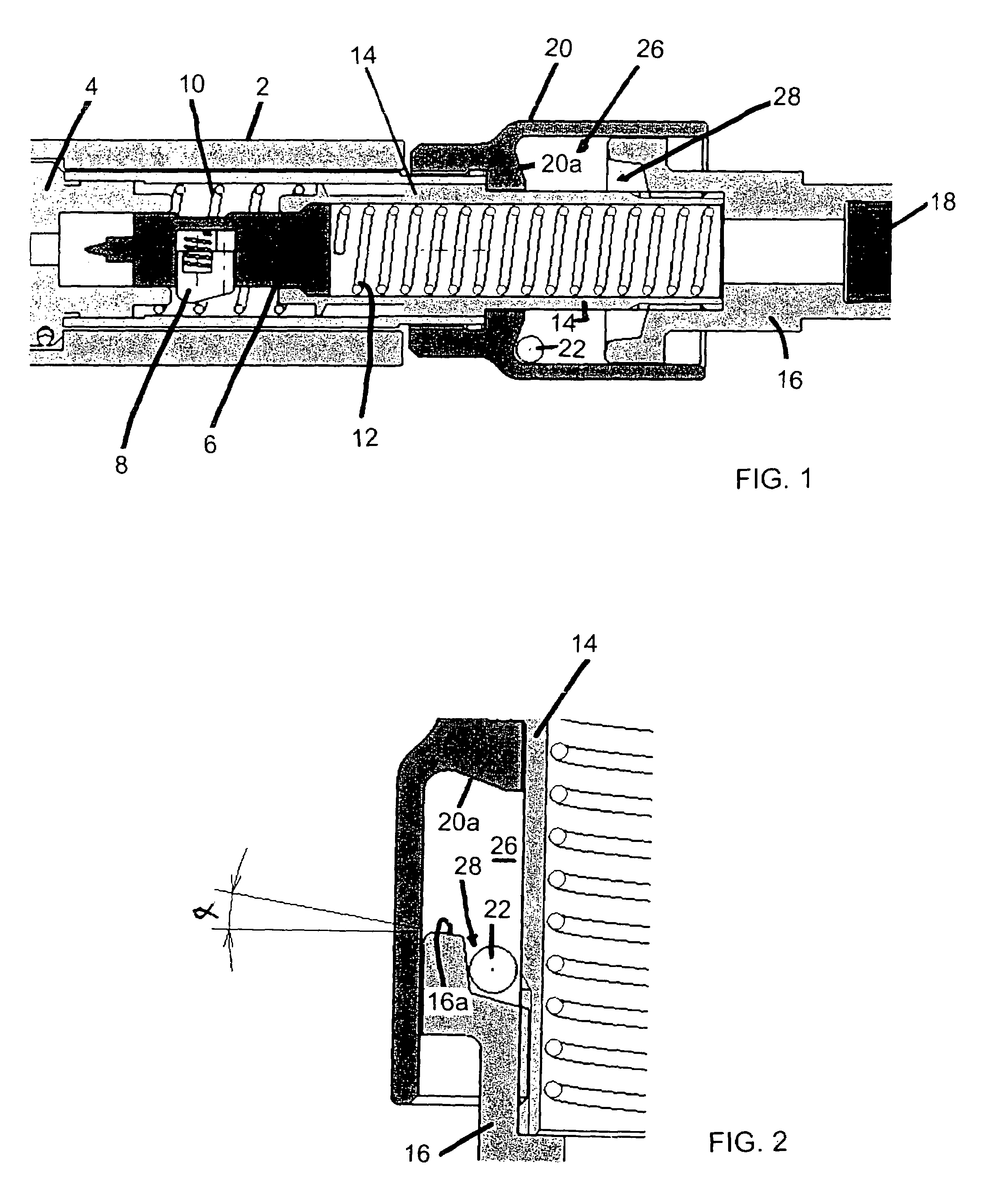
[0022]A pole tool in accordance with the preferred embodiment of the invention is of the type disclosed in U.S. Pat. No. 5,465,893 discussed above and only those parts of the tool which relate to the improvement provided by the present invention will be described in detail. FIG. 1 shows schematically the rear part of the tool housing 2. A barrel (not shown) slidably mounted in the forward part of the housing contains a fastener driving piston and a charge chamber is formed at the rear end of the barrel. The barrel is biased into a forwards position by a compression spring mounted within the housing. A receiver body 4 for receiving an explosive charge carried by a charge strip in the manner illustrated in U.S. Pat. No. 5,465,893 and also in EP 1197301 is mounted in the housing 2 rearwardly of the rear end of the barrel when in a forwards position.

[0023]The receiver body 4 mounts a firing pin 6 which is held in a retracted READY position (as shown in FIG. 1) by a retractable spring lo...


PUM

PropertyMeasurementUnit
angleaaaaaaaaaa
anglesaaaaaaaaaa
angleaaaaaaaaaa

Abstract

An explosively actuated tool for driving a fastener into a substrate is mountable to the end of a pole-like handle to permit manipulation and actuation of the tool from a remote position. Actuation of the tool occurs by pushing the forward end of a barrel of the tool against the substrate using the handle and then pushing forwardly the handle which loads and then releases a tiring mechanism of the tool to fire the charge. The tool has a safety lock device for inhibiting loading of the firing mechanism sufficiently to initiate firing unless the tool is orientated upwardly into a vertical or near vertical orientation.

Description

RELATED APPLICATIONS[0001]The present application is based on, and claims priority from, Australian Application Serial Number 2003903682, filed Jul. 16, 2003, the disclosure of which is hereby incorporated by reference herein in its entirety.BACKGROUND OF THE INVENTION[0002]1. Field of the Invention[0003]The present invention relates to an explosively actuated tool for driving a fastener, such as a pin, into a substrate, for example of concrete or steel.[0004]2. Description of the Prior Art[0005]Explosively actuated tools for driving a fastener, such as a pin, into a hard substrate, such as of concrete or steel, are in common use and operate by detonation of an explosive charge. In most prior tools of this type, detonation of the charge drives a piston within a barrel of the tool and the piston, in turn, drives the fastener which is positioned within the forward end of the barrel prior to firing. Tools of this general type will typically have a pistol grip and the tool is actuated b...

Claims


Application Information

Patent Timeline
Patent Type & Authority Patents(United States)
IPC IPC(8): B21J15/28B27F7/17B25C1/10B25C1/14B25C1/18
CPCB25C1/10
Inventor MCCULLOUGH, DAVID JOHN
Owner ILLINOIS TOOL WORKS INC
Why Eureka
Try Eureka