Waterproof electrical connector

a technology of electrical connectors and waterproof shields, applied in the field of electrical connectors, can solve the problems of affecting the waterproof character and shielding effect of the waterproof shield, the metallic shield may electrically interfere with the antenna, and the metallic shield may tend to be shorted

Active Publication Date: 2017-06-08
FOXCONN INTERCONNECT TECH LTD
View PDF9 Cites 15 Cited by
  • Summary
  • Abstract
  • Description
  • Claims
  • Application Information

AI Technical Summary

Benefits of technology

[0006]Accordingly, the object of the present invention is to provide an electrical connector with a terminal module enclosed within an insulative shield wherein the terminal module includes a plurality of terminals embedded within an insulative base. The insulative main body forms a rear mounting standing part and a front mating tongue part extending forwardly from the rear mounting standing part. The insulative shield forms a rearward step against a forward shoulder of the base portion so as to prevent further forward movement of the insulative main body relative to the insulative shield. One of the insulative shield and the insulative main body forms a locking lug engaged within a locking recess in the other of the insulative shield and the insulative main body so as to prevent rearward movement of the insulative main body relative to the insulative shield. The insulative shield further includes a pair of mounting legs which are located above the bottom face of the insulative shield and located by two lateral sides of the insulative main body.

Problems solved by technology

Anyhow, practically on one hand because the metallic exterior shield is formed by sheet metal, thus inevitably having s a seam after forming and the corresponding inferior waterproof character and shielding effect.
On the other hand, the metallic shield may electrically interfere with the antenna if the antenna part is located too close to the connector.
Moreover, the metallic shield may tend to be shorted if some dusts improperly touch and link the metallic shield and other electronic component.

Method used


Image

  • Waterproof electrical connector
  • Waterproof electrical connector
  • Waterproof electrical connector

Examples


Embodiment Construction

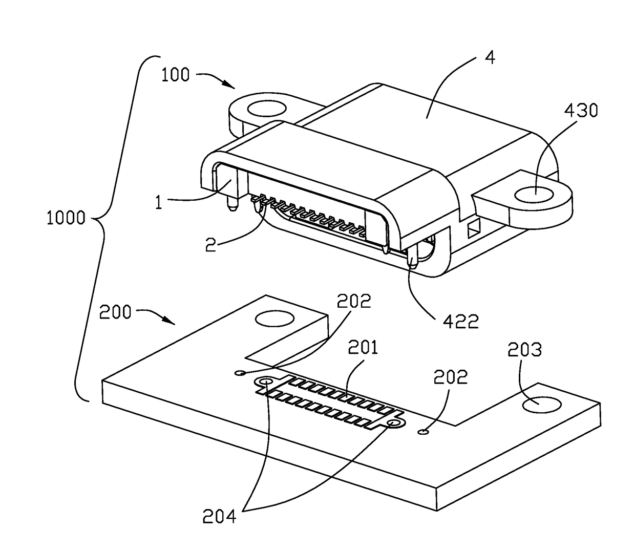
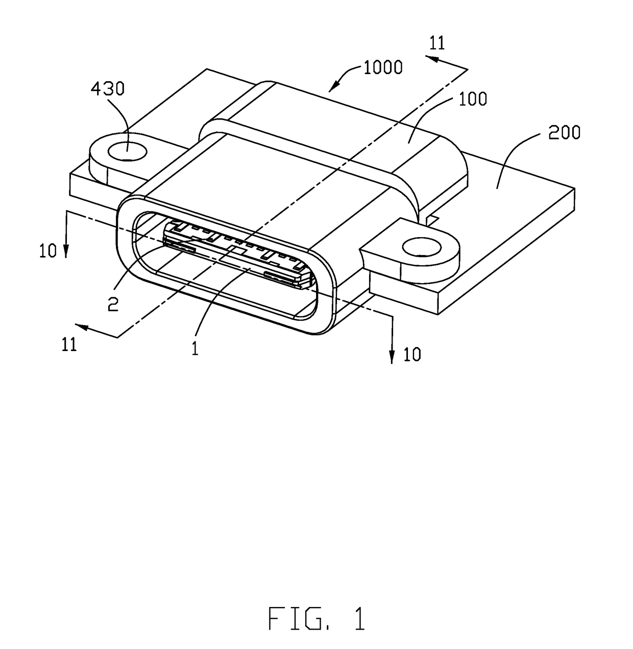
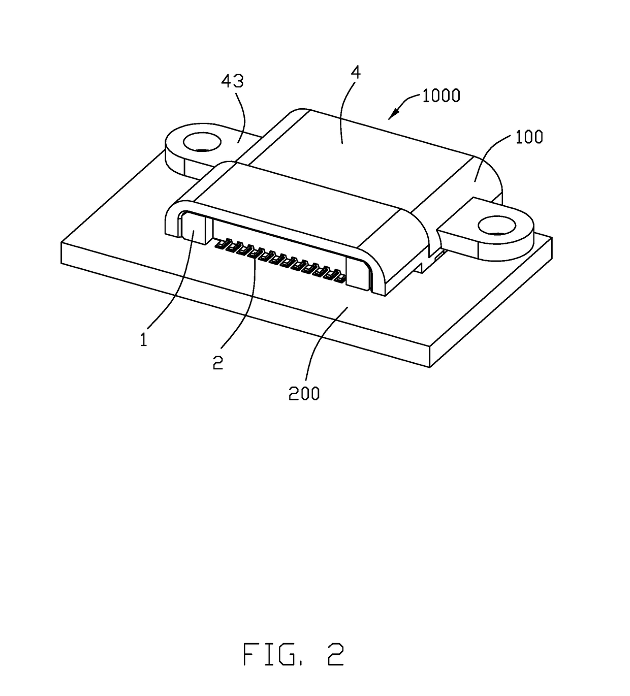
[0019]Reference will now be made in detail to the preferred embodiment of the present invention. Referring to FIGS. 1 to 11, an electrical connector assembly 1000 includes an electrical connector 100 mounted upon and within a cutout 205 an external PCB 200 wherein the electrical connector 100 is mated and withdrawn with a complementary plug connector along the front-to-back direction, is mounted to the PCB 200 in a vertical direction perpendicular to the front-to-back direction. A transverse direction is perpendicular to both the front-to-back direction and the vertical direction. The electrical connector includes a terminal module (not labeled) composed of an insulative main body 1, which is essentially composed of a rear mounting standing part (not labeled) and a front mating tongue part (not labeled) extending forwardly from the rear mounting standing part, and a plurality of conductive terminals 2 associated within the insulative main body 1, a metallic shielding plate 3 embedde...


PUM


Abstract

An electrical connector with a terminal module enclosed within an insulative shield wherein the terminal module includes a plurality of terminals embedded within an insulative main body. The insulative main body forms a rear mounting standing part and a front mating tongue part extending forwardly from the rear mounting standing part. The insulative shield forms a rearward step against a forward shoulder of the base portion so as to prevent further forward movement of the base portion relative to the insulative shield. The insulative main body forms a protrusion and the insulative shield forms a securing hole to receive said protrusion for securing the insulative shield and the terminal module together.

Description

BACKGROUND OF THE INVENTION[0001]1. Field of the Invention[0002]The present invention relates to an electrical connector, and particularly to a USB (Universal Serial Bus) type C connector with a reinforced structure thereof by an insulative shell with the unitarily formed mounting legs in place of a metallic shell.[0003]2. Description of Related Art[0004]USB type C specification was issue on Aug. 11, 2014, which and hundreds of designs are made based upon. The Chinese patent CN204315771 discloses a USB Type C receptacle connector essentially in compliance with the corresponding specification. Anyhow, practically on one hand because the metallic exterior shield is formed by sheet metal, thus inevitably having s a seam after forming and the corresponding inferior waterproof character and shielding effect. On the other hand, the metallic shield may electrically interfere with the antenna if the antenna part is located too close to the connector. Moreover, the metallic shield may tend t...

Claims


Application Information

Patent Timeline
Patent Type & Authority Applications(United States)
IPC IPC(8): H01R13/52H01R4/02H01R12/71H01R24/60H01R13/405
CPCH01R13/5216H01R24/60H01R2107/00H01R12/716H01R4/02H01R13/405H01R13/50H01R13/5202H01R13/5213H01R12/7082H01R12/7047H01R12/725
Inventor ZHAO, JUNGU, GUANG-XINGUO, JING-JIE
Owner FOXCONN INTERCONNECT TECH LTD
Why Eureka
Try Eureka