Stapler with rotating handle and use method of stapler

A technology of rotating the handle and stapler, which is applied in the direction of surgical fixation nails, etc., and can solve the problems of complex structure of the cutting stapler, inaccurate cutting and suturing parts, and inability to lock.

Active Publication Date: 2018-02-23
CHANGZHOU XIN NENG YUAN MEDICAL STAPLER
View PDF11 Cites 16 Cited by
  • Summary
  • Abstract
  • Description
  • Claims
  • Application Information

AI Technical Summary

Problems solved by technology

The above-mentioned cutting stapler has a complex structure, and the position cannot be locked when the trigger is used to control the driving rod, resulting in inaccurate cutting and suturing parts

Method used


Image

  • Stapler with rotating handle and use method of stapler
  • Stapler with rotating handle and use method of stapler
  • Stapler with rotating handle and use method of stapler

Examples


Embodiment 1

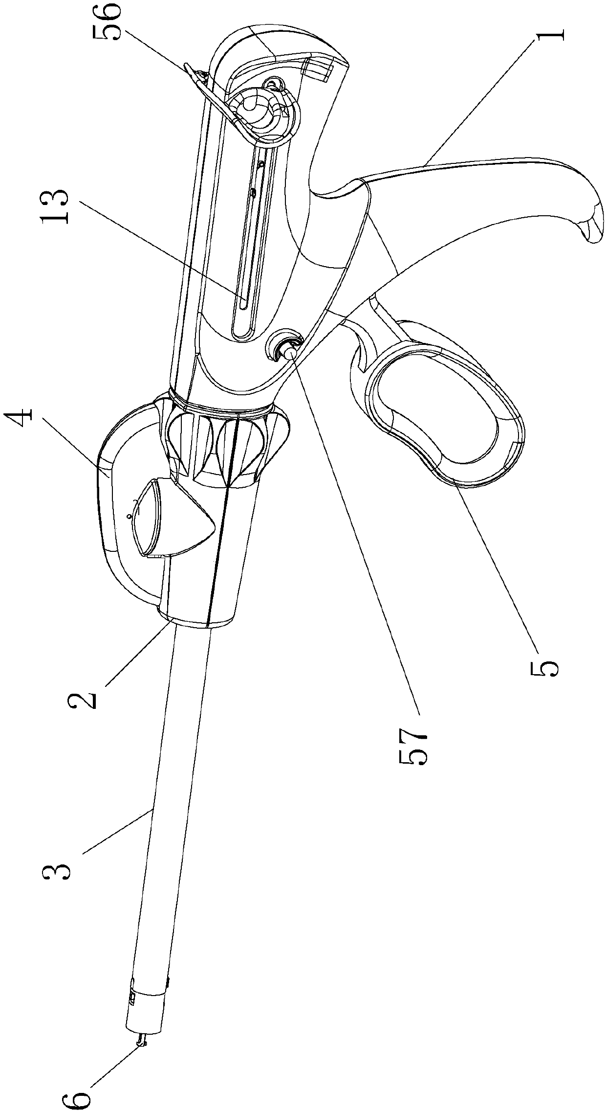
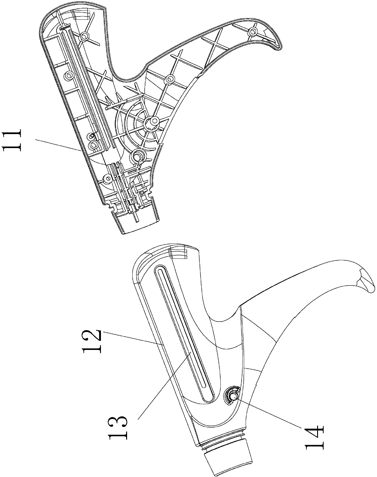
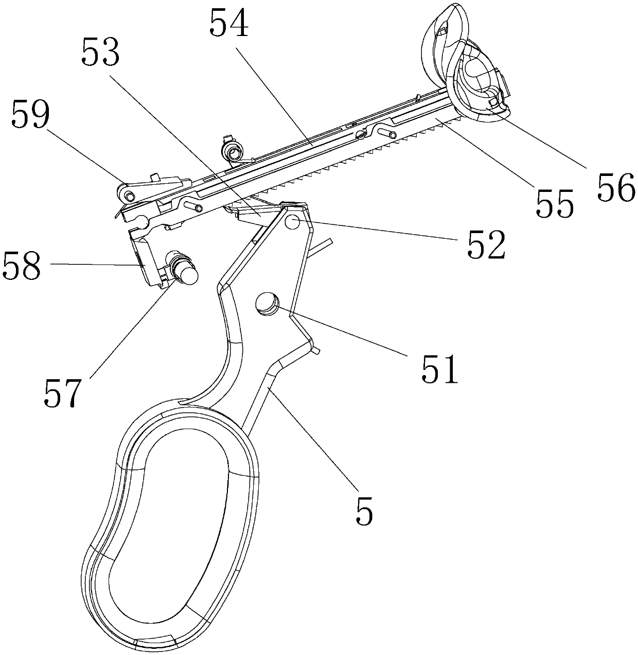
[0071] A stapler with a rotating handle, including a rotating housing, such as figure 1 As shown, the rotating housing includes a handle housing 1, a rotating assembly, a sleeve assembly 3, a dial assembly 4, a push rod 6 and a connecting piece 7, as figure 2 The shown handle housing 1 is formed by fastening and fixing the left handle housing 11 and the right handle housing 12; the handle housing 1 is provided with a driving mechanism, and the driving mechanism is composed of a power device, a reset device, a safety device and an interlocking device. parts, such as image 3 As shown, the power device includes a transmission rack 54 slidingly matched with the handle housing 1, a rack transmission member 53, and a trigger 5 pivotally engaged with the handle housing 1. The lower part of the transmission rack 54 slides along the transmission rack 54. A plurality of wedge-shaped teeth 541 are arranged in the direction; the middle part of the trigger 5 is pivotally connected with ...

Embodiment 2

[0087] A method for using a stapler, comprising the steps of:

[0088] A. Insert the articulated actuator assembly 8 into the rotary handle so that the tail end of the actuator housing 84 is inserted into the front end of the connecting pipe 32, the front end of the connecting piece 7 is engaged with the tail end of the steering pull piece 87, and the push rod 6 The front end extends into the actuator housing 84 and engages with the push rod plug 63 of the push tube 6, and the tail end of the actuator housing 84 engages with the annular limit boss 322 on the inner wall of the connecting pipe 32, and the ring at the tail end of the actuator housing 84 Push the boss 846 to drive the anti-rotation piece 47 to move backward, and then push the transmission tube 35, the sliding seat 23, and the reset push button to move backward 596, so that the second end 592 of the firing interlock block 59 is upturned, and the firing interlock block 59 is released. The locking of the transmission...


PUM


Abstract

The invention relates to a stapler with a rotating handle and a use method of the stapler. The rotating handle of the stapler includes a handle shell, a rotating component, a sleeve pipe component, apush rod and a connection piece. A drive mechanism is arranged in the handle shell, the tail end of the connection piece is cooperated with a dial button component through transmission, and the connection piece thus slides in the sleeve pipe component when the dial button component rotates; the drive mechanism is cooperated with a transmission rack through a trigger, and the pushing speed and accuracy of the push rod can be accurately controlled; the rotating component is cooperated with the rack through a transmission gear through transmission, rotary motion is converted into linear motion, control is facilitated, and the stapler is easy to control.

Description

technical field [0001] The invention relates to the technical field of medical equipment, in particular to a stapler with a rotating handle and a usage method thereof. Background technique [0002] In the prior art, a stapler is a device used in medicine to replace manual suturing, and its main working principle is to use titanium nails to separate or anastomose tissues. Compared with traditional manual suture, instrument suture has the advantages of simple and convenient operation, one-time use, avoiding cross infection, tight suture, moderate elasticity and less side effects, which can effectively reduce surgical complications and so on. [0003] Patent authorization announcement number CN103315788B discloses a cutting stapler suitable for minimally invasive surgery, which includes the following components: a housing with a drive mechanism inside; a rotating head that is rotatably mounted on the front end of the housing; a sleeve with a rear end It is connected with the r...

Claims


Application Information

Patent Timeline
Patent Type & Authority Applications(China)
IPC IPC(8): A61B17/072
CPCA61B17/07207A61B2017/07285
Inventor 万建峰马博平
Owner CHANGZHOU XIN NENG YUAN MEDICAL STAPLER
Why Eureka
Try Eureka