Method and apparatus for anodizing

a technology of anodizing and metallic surfaces, applied in the field of electrochemical processing, can solve the problems of increasing the size and number of bubbles, serious interference, and hydrogen bubble formation on the surface of materials, and achieves the effects of preventing gradual or gradual occlusion, accelerating effective anodizing, and improving quality

Inactive Publication Date: 2001-04-17
ELECTROPLATING TECH
View PDF1 Cites 17 Cited by
  • Summary
  • Abstract
  • Description
  • Claims
  • Application Information

AI Technical Summary

Benefits of technology

It is a still further object of the invention to provide a substantially solid wiper blade biased against an anodic work surface in a manner such that the solid wiper blade blocks forward movement of the electrolyte along the surface of the workpiece forcing used solution away from the surface and causing fresh solution to flow in behind the wiping blade, thus effectively forcing exchange of coating solution to prevent overheating of such solution adjacent the anodic surface.
It is a still further object of the invention to provide a substantially solid wiping blade having a restricted cross section and resilient so that the blade when biased against an anodic coating surface in a flexed configuration bears against the surface and both dislodges oxygen bubbles from such surface, blocks the passage of electrolytic solution past such resilient blade and steadies the material being coated.
It is a still further object of the invention to combine a substantially solid wiper blade with a perforated cathode adjacent to an anodic work surface to maximize the efficiency of interchange of electrolyte by the wiper blades.

Problems solved by technology

As detailed more particularly in U.S. application Ser. Nos. 08 / 179,520 filed Jan. 10, 1994 and 08 / 316,530, filed Sep. 30, 1994, the disclosures of which are hereby expressly incorporated into and made a part of this application, it has been found by the present inventors as well as others that a serious problem in electrolytic plating is the formation of bubbles of hydrogen on the surface of the material being coated and that it is conducive to good coating results to remove such hydrogen bubbles from a cathodic work surface.
If nothing is done to remove the hydrogen from the coating surface during the coating process, coating will usually continue, but it may be seriously interfered with by the increasing size and number of bubbles.
Difficulty is also often encountered in anodizing with excessive heating of the solution layer next to the anode due to the high currents used in the process and the resistance of the dielectric metal oxide layer on the surface of the workpiece as such oxide layer thickens.
A second significant problem which has been long recognized in electrolytic coating baths is depletion of the electrolytic solution as coating progresses.
The coating bath next to a workpiece may in particular become locally depleted of coating metal ions.
A further problem in the continuous coating of a flexible material such as sheet, strip and wire products is that the efficiency of electroplating usually increases as the spacing between the electrodes, one of which is the material to be coated, decreases.
Contact rolls are spaced throughout the apparatus but are not used for the purposes of removing gas bubbles from the metal strip.
The Cooke et al. patent does not fully explain why increasing the turbulence of the electrolyte flow bolsters the coating efficiency.
There is no device used for the specific purpose of removing gas from the vicinity of the strip, including no flexible wiping blades.
Exactly what sort of shape this would be is not clear, but it seems clear in either case that the resiliency would cause the triangular structure shown to be compressed inwardly, forming a seal between the blade and the coated surface interfering with the electrocoating operation.
Because electrolyte agitation requires a much larger pump, however, the added power consumption negates the cost-saving benefits from the removal of the gas.
Problems stemming from this technique include supplying sufficient power to the metal web and the added maintenance cost of the unusual design.
This technique, like the first technique described, requires a larger pump and therefore suffers from the same disadvantages.
It is stated the process is not well suited for chromium plating, because high current densities do not increase the plating out of chromium.
It is also stated that chromium is difficult to use in the invention because chromium deposits slowly regardless of current density so that the deposition is slow and the advantages of gap plating are not fully attained.

Method used


Image

  • Method and apparatus for anodizing
  • Method and apparatus for anodizing
  • Method and apparatus for anodizing

Examples


Embodiment Construction

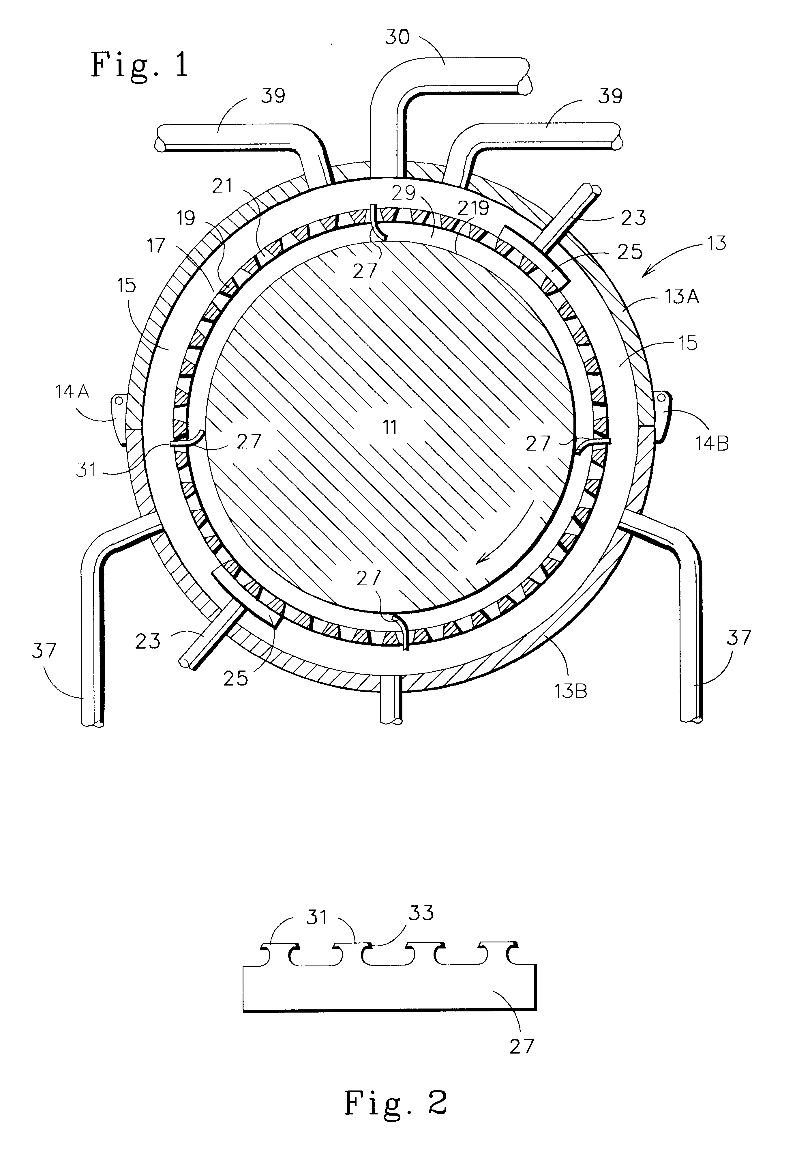
Various ways of removing hydrogen bubbles from the surface of a cathodic workpiece as well as oxygen bubbles from anodic workpieces and preventing electrolyte solution depletion have been developed in the past.

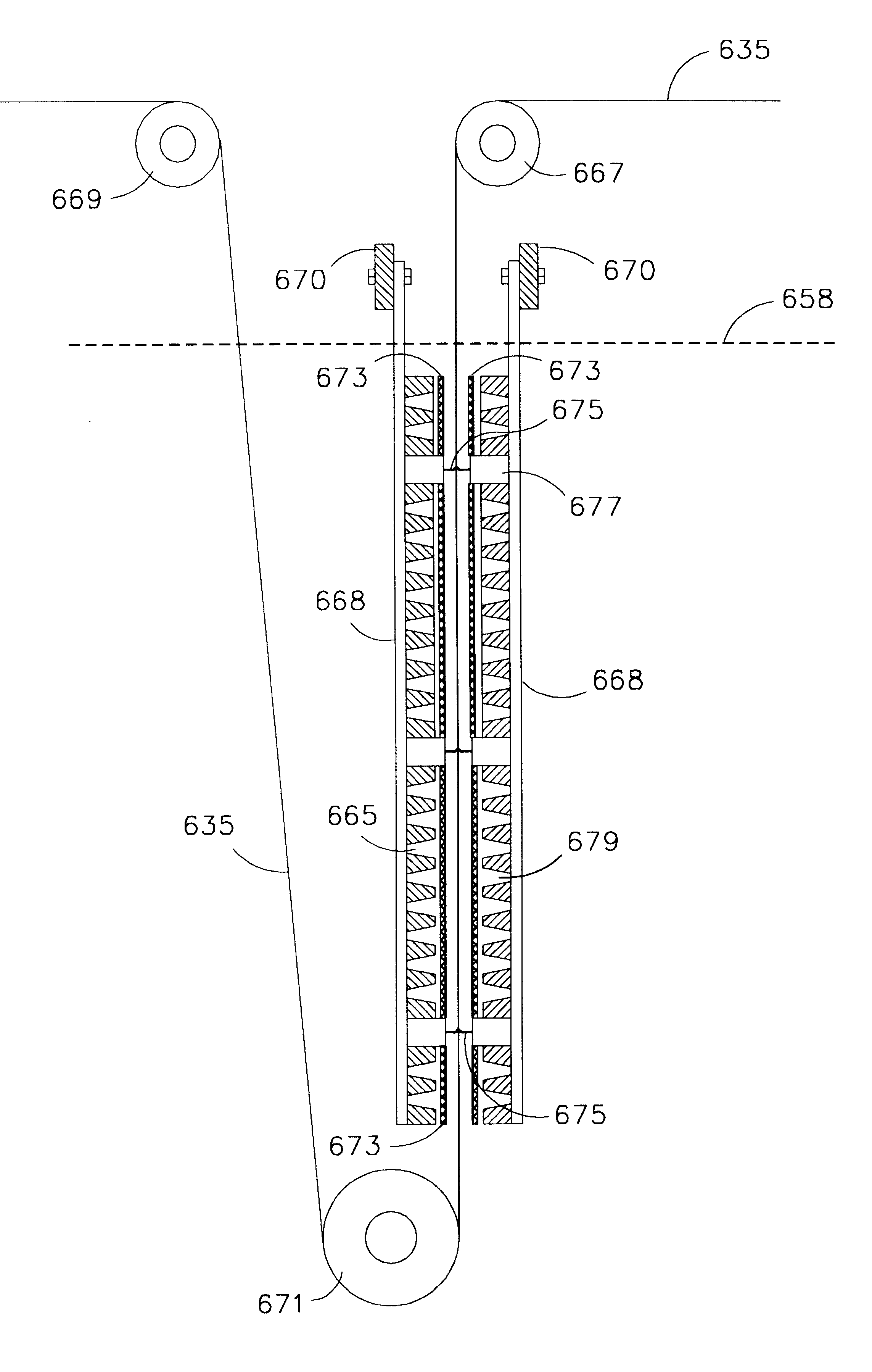
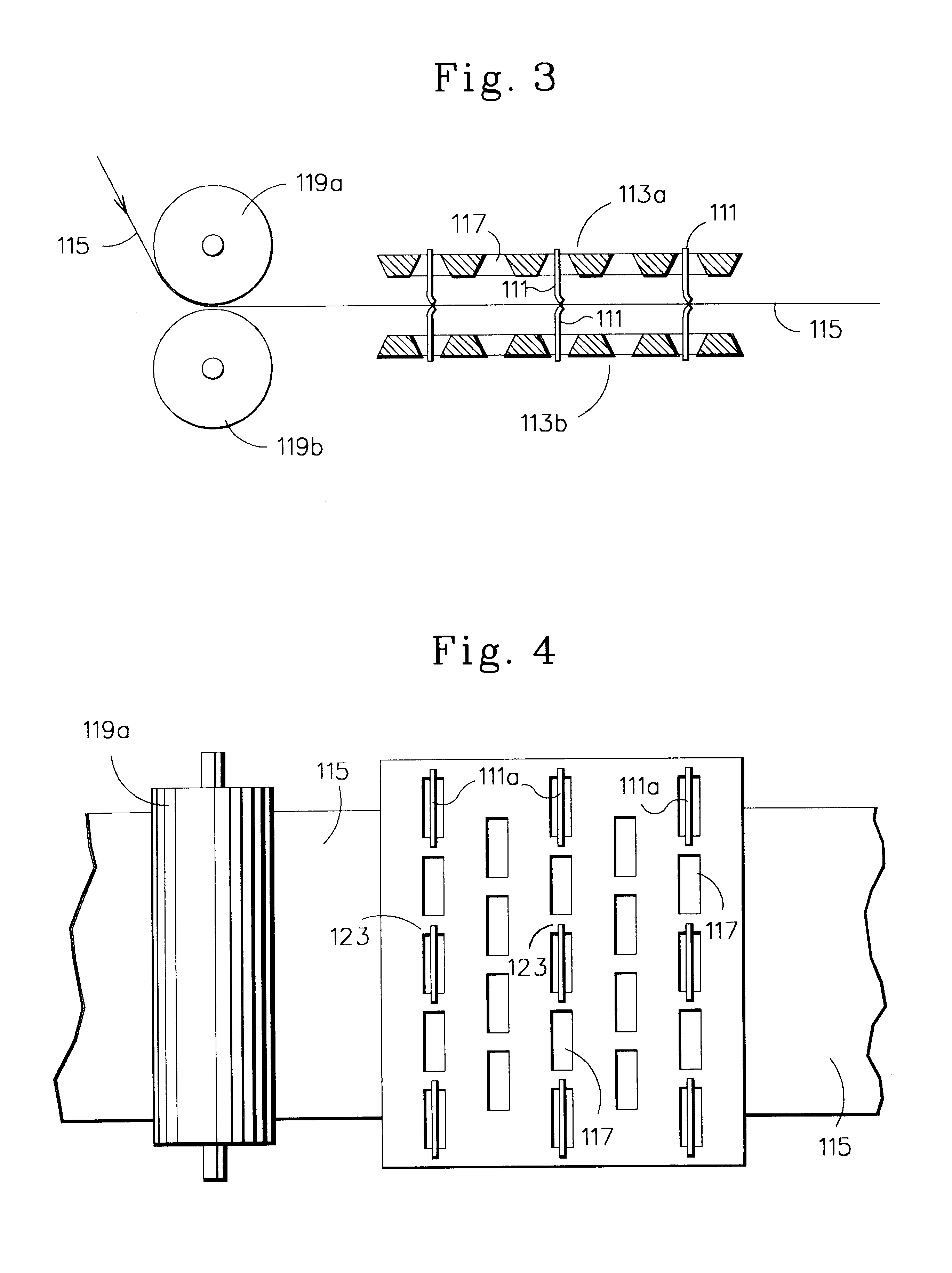
Likewise, it has been realized for many years that the rapidity and quality of electrochemical processing could be, at least theoretically, increased by spacing the processing electrodes as close to the workpiece surface to be coated or otherwise treated as possible. Where both the workpiece and the electrode are structurally rigid, the choice of such distance may be determined by the breakdown potential of the electrolytic solution. However, in the continuous coating of long lengths of sheet, strip, wire and the like, a further complication occurs in that the flexible material to be coated tends to oscillate, thus forcing the coating electrodes to be fairly widely spaced from the workpiece to prevent accidental arcing.

The present Applicants have discovered through careful exp...


PUM

PropertyMeasurementUnit
thicknessaaaaaaaaaa
distanceaaaaaaaaaa
widthaaaaaaaaaa

Abstract

A resilient dielectric wiper blade is mounted between electrodes and a workpiece, particularly in an anodizing operation, to wipe bubbles of oxygen from the anodic work surface, to remove a surface layer of excessively heated electrolytic solution and replace with fresh cooler solution, and in the case of flexible strip processing, to stabilize the strip between cathodes. The resilient dielectric wiper blade is preferably used with perforated electrodes to facilitate removal of overheated electrolytic solution and replace with freshly circulated solution.

Description

BACKGROUND OF THE INVENTION(1) Field of the InventionThis invention relates to electrochemical processing of the surfaces of metal substrates and the like to provide corrosion-resistant and decorative coatings from chemical treatment baths. More particularly, this invention relates to the so-called anodizing of metallic surfaces and more particularly to the use of a substantially solid flexible wiper blade during such anodizing.(2) Prior ArtAs detailed more particularly in U.S. application Ser. Nos. 08 / 179,520 filed Jan. 10, 1994 and 08 / 316,530, filed Sep. 30, 1994, the disclosures of which are hereby expressly incorporated into and made a part of this application, it has been found by the present inventors as well as others that a serious problem in electrolytic plating is the formation of bubbles of hydrogen on the surface of the material being coated and that it is conducive to good coating results to remove such hydrogen bubbles from a cathodic work surface. If nothing is done t...

Claims


Application Information

Patent Timeline
Patent Type & Authority Patents(United States)
IPC IPC(8): C25D7/06
CPCC25D17/008C25D11/005
Inventor VAN ANGLEN, ERIK S.KEENEY, HAROLD M.FORAND, JAMES L.
Owner ELECTROPLATING TECH
Why Eureka
Try Eureka