Method and apparatus for cooling a module portion

a technology for cooling modules and components, applied in cooling/ventilation/heating modifications, electrical apparatus casings/cabinets/drawers, instruments, etc., can solve the problems of insufficient prior art configuration and cooling methods of electronic modules and their cabinets, side-to-side cooling patterns have the disadvantage of pre-heating air for each successive chassis,

Active Publication Date: 2006-03-21
SMART EMBEDDED COMPUTING INC
View PDF12 Cites 72 Cited by
  • Summary
  • Abstract
  • Description
  • Claims
  • Application Information

AI Technical Summary

Problems solved by technology

The side-to-side cooling pattern has the disadvantage of pre-heating air for each successive chassis when chassis are placed side-by-side as is common in telecommunications and other embedded applications.
As processor speeds increase and electronic modules generate more thermal energy, prior art configurations and methods of cooling electronic modules and their cabinets will become inadequate.

Method used


Image

  • Method and apparatus for cooling a module portion
  • Method and apparatus for cooling a module portion
  • Method and apparatus for cooling a module portion

Examples


Embodiment Construction

[0010]In the following detailed description of exemplary embodiments of the invention, reference is made to the accompanying drawings (where like numbers represent like elements), which illustrate specific exemplary embodiments in which the invention may be practiced. These embodiments are described in sufficient detail to enable those skilled in the art to practice the invention, but other embodiments may be utilized and logical, mechanical, electrical and other changes may be made without departing from the scope of the present invention. The following detailed description is, therefore, not to be taken in a limiting sense, and the scope of the present invention is defined only by the appended claims.

[0011]In the following description, numerous specific details are set forth to provide a thorough understanding of the invention. However, it is understood that the invention may be practiced without these specific details. In other instances, well-known circuits, structures and techn...


PUM


Abstract

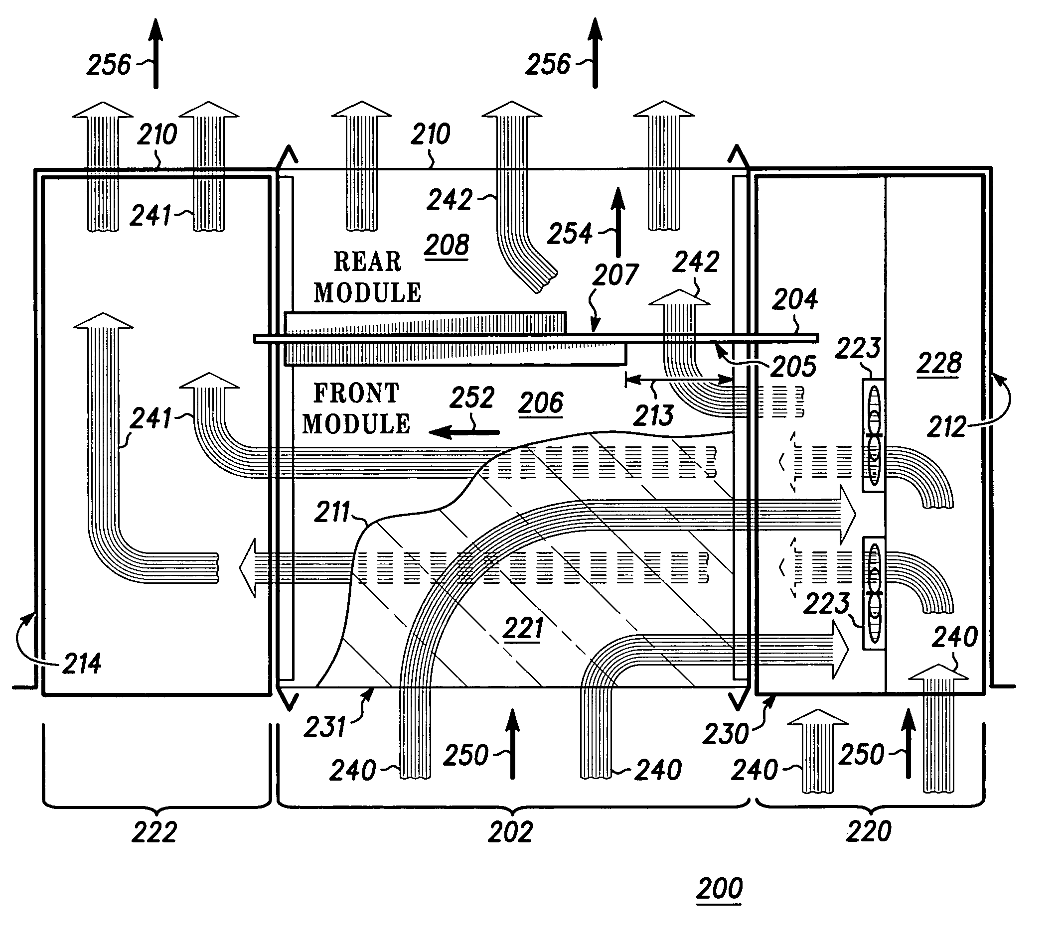
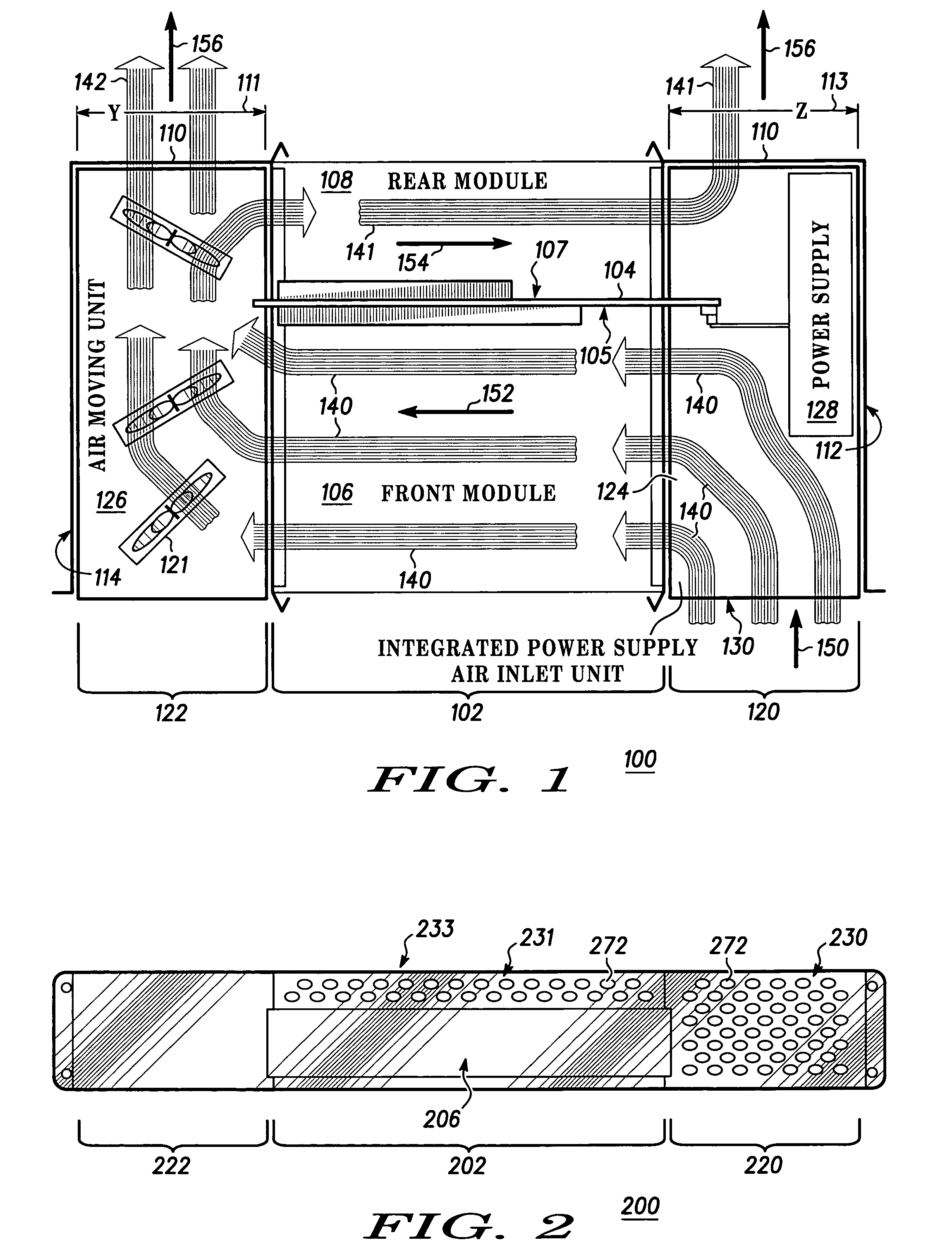
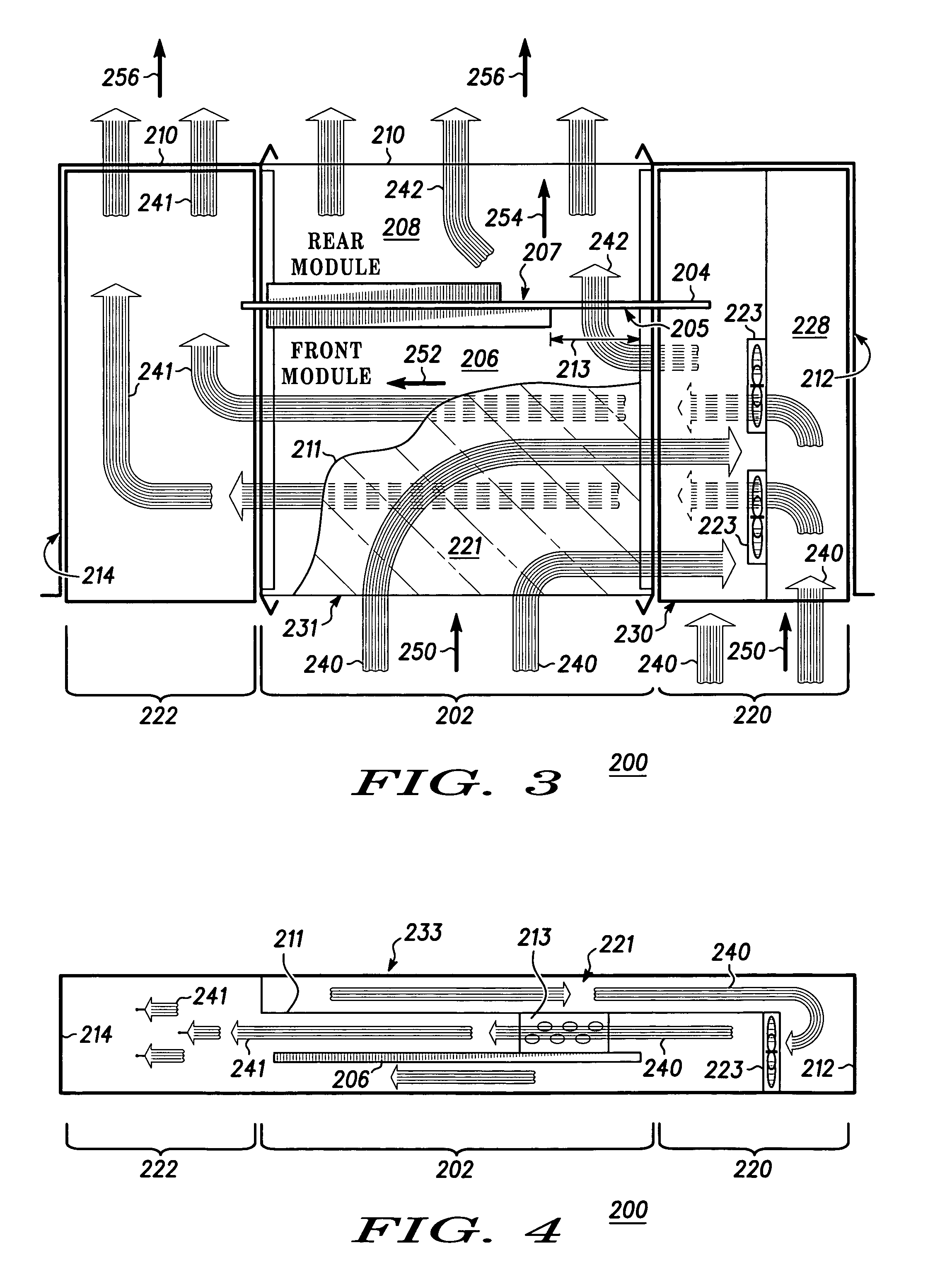
A method of cooling a module portion (202) of an embedded computer chassis (200), where the module portion comprises a front module (206) coupled to a front portion of a backplane (204), and a rear module (208) coupled to a rear portion of the backplane, where the front module and the rear module are horizontally disposed, the method includes drawing a cooling air mass (240) into the embedded computer chassis through a front surface (230) of a first interspace region (220) and an upper front surface (231) of a second interspace region (221) in a direction substantially perpendicular (250) to the front surface and the upper front surface. A third interspace region (222) receives a first portion of the cooling air mass (241), the cooling air mass exhausting from the embedded computer chassis through a rear surface (210) in a direction substantially perpendicular (256) to the rear surface.

Description

RELATED APPLICATIONS[0001]Related subject matter is disclosed in U.S. patent application entitled “INTEGRATED POWER SUPPLY AND AIR INLET UNIT” having application Ser. No. 10 / 927,881 and filed on the same date herewith and assigned to the same assignee.BACKGROUND OF THE INVENTION[0002]Existing electronic equipment cabinets generally employ forced air convection cooling of electronic modules mounted in chassis within the cabinet. Many prior art cabinet and chassis configurations circulate cooling air in a side-to-side configuration. The side-to-side cooling pattern has the disadvantage of pre-heating air for each successive chassis when chassis are placed side-by-side as is common in telecommunications and other embedded applications. As processor speeds increase and electronic modules generate more thermal energy, prior art configurations and methods of cooling electronic modules and their cabinets will become inadequate.[0003]Accordingly, there is a significant need for an apparatus...

Claims


Application Information

Patent Timeline
Patent Type & Authority Patents(United States)
IPC IPC(8): H05K7/20
CPCH05K7/20909G06F1/20
Inventor WONG, HENRY
Owner SMART EMBEDDED COMPUTING INC
Why Eureka
Try Eureka