Valve stem remover and installer tool kit

a technology for installing tools and valve stems, which is applied in the direction of manufacturing tools, metal-working equipment, metal-working equipment, etc., can solve the problems of human employing the tool to remove valve stems, and achieve the effect of convenient stocking

Inactive Publication Date: 2006-03-28
DETZEL DAVE
View PDF7 Cites 8 Cited by
  • Summary
  • Abstract
  • Description
  • Claims
  • Application Information

AI Technical Summary

Benefits of technology

[0005]The present invention is directed to a kit for removal and insertion of valve stems for tubeless tires into the rim of a wheel while the tire remains mounted on the rim. The present invention is a simple kit which does not require complicated mechanical devices for the removal or insertion of the valve stem, is easily stocked, and can be done with human power alone. Further, the removal tool has a J-shaped end which does not present a sharp or hooked end, which presents danger to humans employing the tool to remove valve stems.

Problems solved by technology

Further, the removal tool has a J-shaped end which does not present a sharp or hooked end, which presents danger to humans employing the tool to remove valve stems.

Method used


Image

  • Valve stem remover and installer tool kit
  • Valve stem remover and installer tool kit
  • Valve stem remover and installer tool kit

Examples


Embodiment Construction

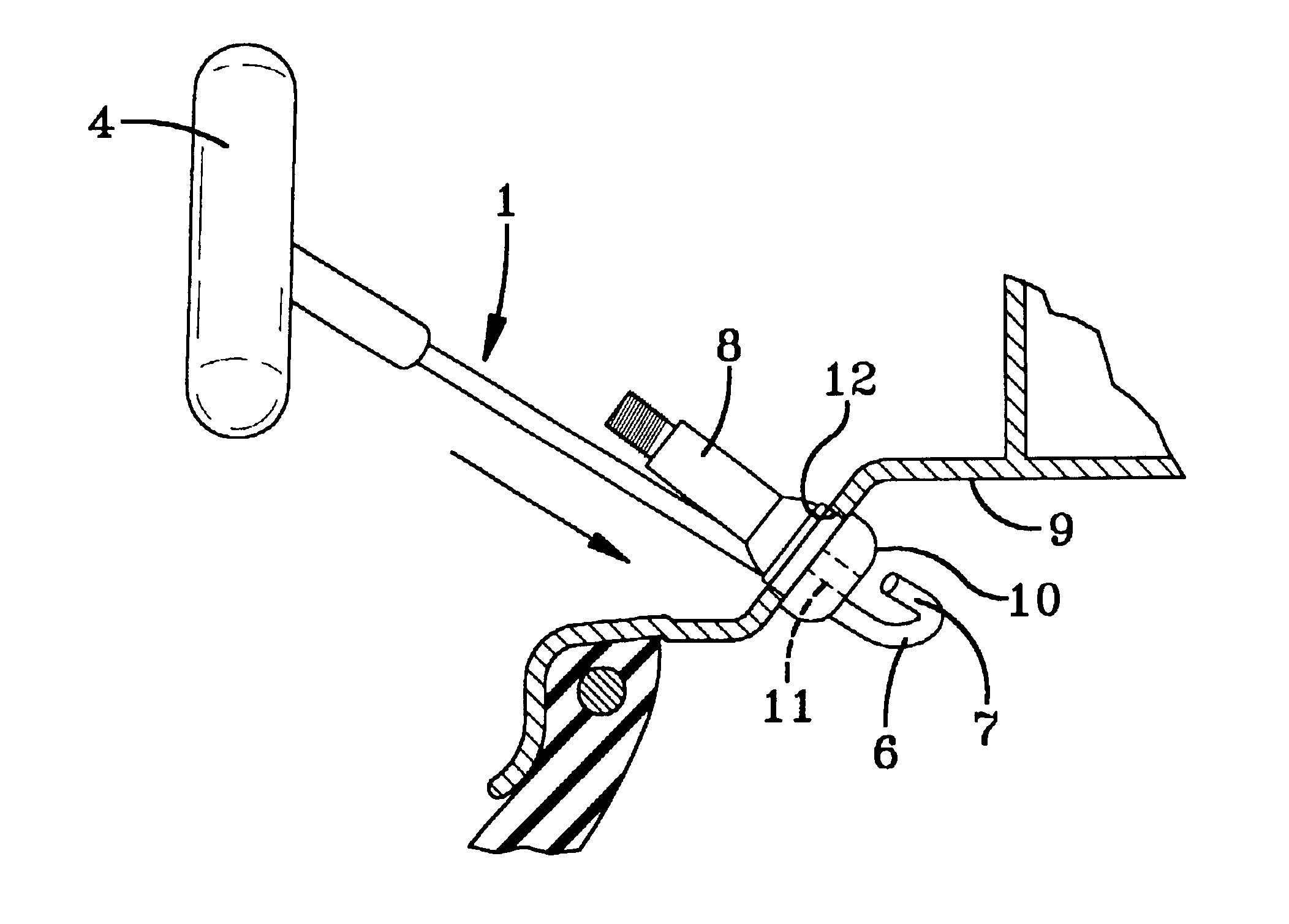
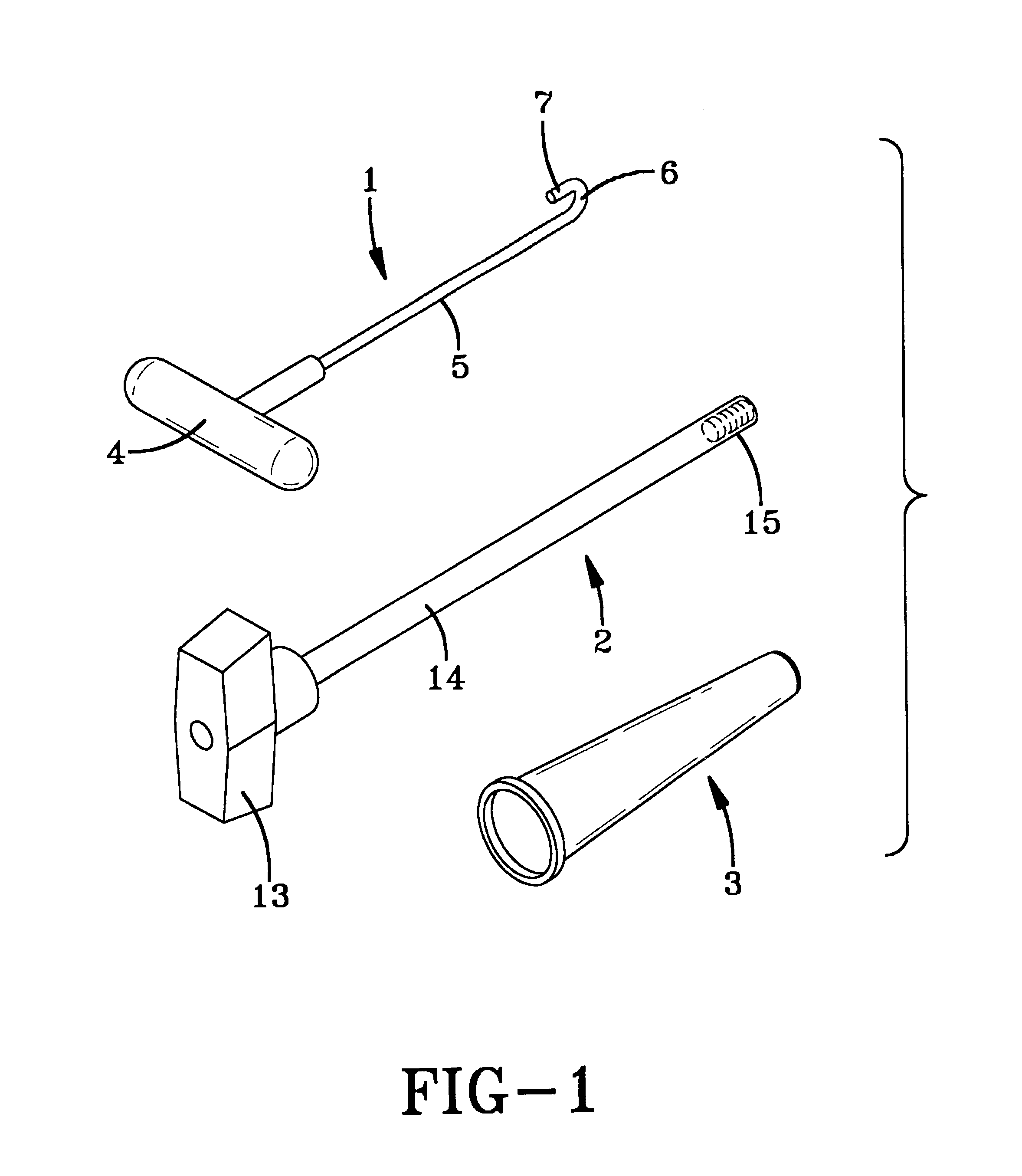
[0013]FIG. 1 illustrates the basic components of the kit, namely a valve stem removal tool 1, a valve stem insertion tool 2, and a valve stem insertion sleeve 3 which works in conjunction with the insertion tool 2.

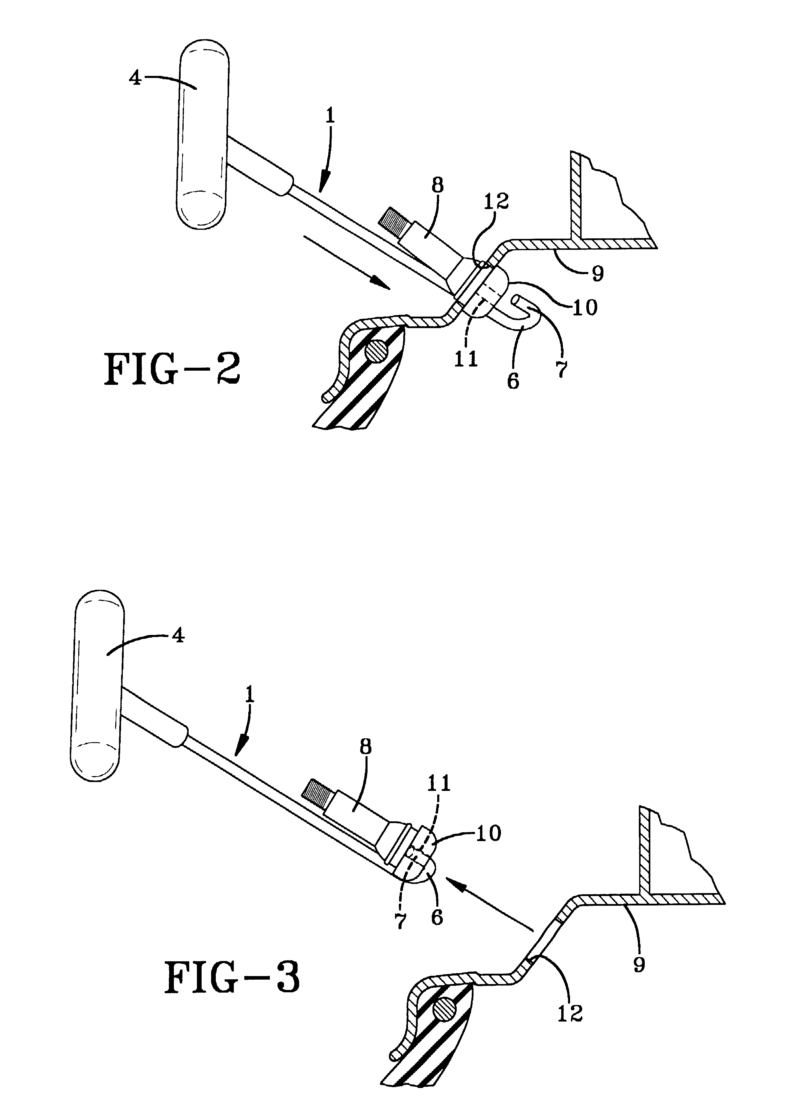
[0014]As shown in FIG. 1, the valve stem removal tool 1 has a handle 4 at one end connected to a rod 5 and a “J”-shaped engagement end 6 in which the short end of the “J” is of sufficient curvature and length to fit into the opening in the bulbous end of a valve stem which projects into the interior of the tubeless tire. Preferably, the short end of the “J” is blunt, i.e., not sharp or pointed, although some or a slight curvature, such as a dome shape, is acceptable. To remove a valve stem, the tool is inserted between the valve stem 8 and the opening in the wall of the tire 12. The “J” shape of the tool facilitates the insertion of the tool between the valve stem and the opening. As a practical matter, the size of the “J” is such that a tool which about 15.5 centimeters i...


PUM

PropertyMeasurementUnit
lengthaaaaaaaaaa
lengthaaaaaaaaaa
lengthaaaaaaaaaa

Abstract

The present invention is a simple kit for removal and insertion of valve stems for tubeless tires while the tire remains mounted on the rim.

Description

[0001]This application claims the benefit of provisional application Ser. No. 60 / 292,071, filed May 18, 2001.BACKGROUND OF THE INVENTION[0002]The present invention relates to a kit for the removal and insertion of valve stems on tubeless tire rims of tire wheels while the tire remains mounted on the rim.[0003]Tubeless tires have a tire casing mounted on a wheel rim and a valve stem mounted in a hole in the rim. The stem has a threaded sleeve for attachment of a cap and a spring-biased valve insert for inflating the tire and retaining the air is mounted in the stem. Attached to the sleeve is a bulbous portion of an elastic material, and a groove is placed about the mid-portion of this elastic material to permit the bulbous portion to seat against the inside and outside faces of the rim. The stems are commonly inserted from the inside of the wheel by inserting the stem through the hole and pulling it until the groove in the bulbous portion seats about the hole. This installation requi...

Claims


Application Information

Patent Timeline
Patent Type & Authority Patents(United States)
IPC IPC(8): B23P19/04B25B27/24B25B27/28
CPCB25B27/24B25B27/28Y10T29/53591Y10T29/53596
Inventor DETZEL, DAVE
Owner DETZEL DAVE
Why Eureka
Try Eureka