
Solar powered lighting assembly

a technology of solar energy and lighting assembly, which is applied in the direction of lighting support devices, greenhouse gas reduction, and power-in-place devices, etc., can solve the problems of high installation fees, time-consuming and laborious, and complex installation procedures of external lighting assemblies

Active Publication Date: 2006-03-28
MICHAEL KENNETH GEORGE +1
View PDF8 Cites 86 Cited by
  • Summary
  • Abstract
  • Description
  • Claims
  • Application Information

AI Technical Summary

Problems solved by technology

These kinds of external lighting assemblies often involve complex installation procedures, especially when there is insufficient house or building wiring available to power external lights.
The entire process is time consuming, inconvenient and expensive and the investment made is usually only for the period of time during which a building is occupied.
Further, since industry standard lighting sources are not always the most energy efficient light sources, installation of such lighting sources can result in high installation fees and a substantial increase in associated electricity costs.
Additionally, the use of expensive light sources (e.g. halogen) for outdoor lighting applications can result in costly and disruptive damage and breakage due to adverse environmental conditions.

Method used


Image

  • Solar powered lighting assembly
  • Solar powered lighting assembly
  • Solar powered lighting assembly

Examples


Embodiment Construction

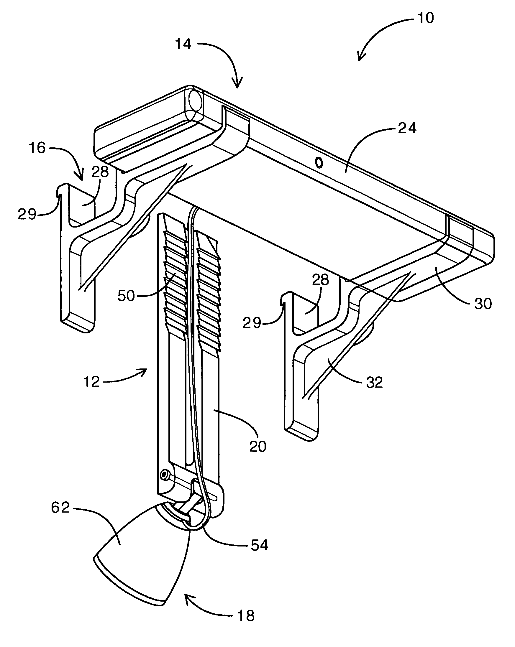
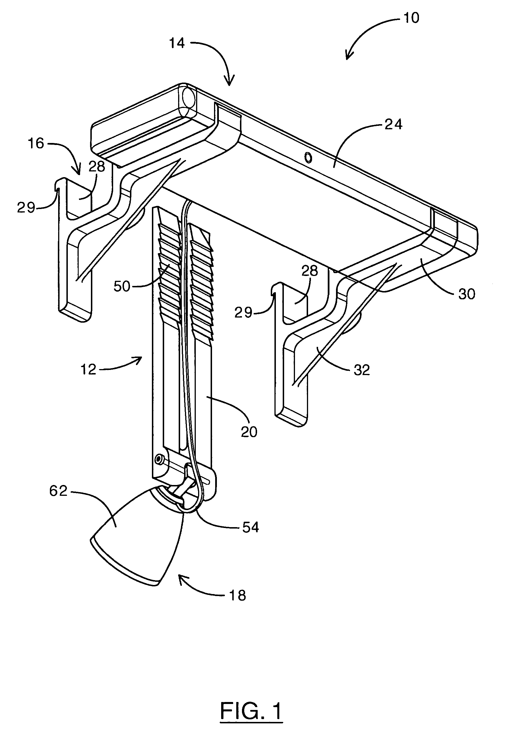
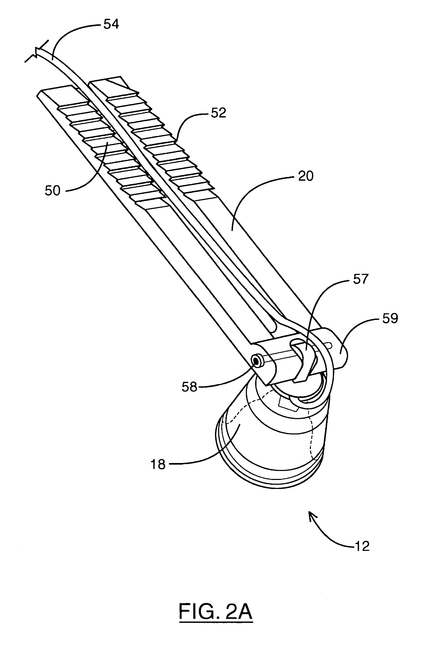
[0032]Reference is first made to FIGS. 1, 2A, 2B, 3A, 3B and 4 that show various views of the solar powered lighting assembly 10 made in accordance with a preferred embodiment of the present invention. Solar powered lighting assembly 10 includes a lamp assembly 12, a solar panel assembly 14 and a pair of mounting brackets 16. Lamp assembly 12 includes a lighting element 18 and a connector arm 20 that is adapted to be removably secured between the outer wall surface 15 of an external wall and the inside wall 17 of an eaves trough 19. Solar panel assembly 14 includes a solar panel array 22, a solar panel housing 24 and a rechargeable power source 26 (FIG. 4). Mounting brackets 16 include an eaves trough connector 28, bracket support arms 30 and a brace element 32 (FIG. 1).

[0033]Lamp assembly 12 includes a lamp element 18 and a connector arm 20. Lamp element 18 (FIG. 3A) includes at least one lamp 60, a lamp housing 62, a lamp shield 64 and a lamp reflector 66. Lamp 60 is preferably an...


PUM


Abstract

A solar powered lighting assembly for attachment to an eaves trough mounted on an outer wall surface includes a lamp, a rechargeable power source, a solar panel assembly, a mounting bracket and a connector arm. The rechargeable power source is connected to the lamp to provide operational power. The solar panel assembly is coupled to the rechargeable power source to provide electrical power for recharging the rechargeable power source. The mounting bracket is coupled to the inside surface of the eaves trough and is used to support the rechargeable power source and the solar panel assembly. The connector arm is coupled to the lamp and is adapted to be removeably coupled in between the eaves trough and the outer wall surface.

Description

[0001]This application claims the benefit under 35 U.S.C. 119(e) of U.S. Provisional Application No. 60 / 428,276, filed Nov. 22, 2002.FIELD OF THE INVENTION[0002]This invention relates to a solar powered lighting assembly, and more particularly to a solar powered lighting assembly adapted to be mounted within an eaves trough.BACKGROUND OF THE INVENTION[0003]Conventional exterior pot-lighting are commonly used to achieve a desirable decorative soft ambient look for the outside of residential and retail buildings. In fact, halogen pot lights and other forms of high quality recessed lights have become the industry standard.[0004]These kinds of external lighting assemblies often involve complex installation procedures, especially when there is insufficient house or building wiring available to power external lights. In such cases, electricians are required to assist in the design and installation processes and permits are required in order to make adjustments to the electrical work in a ...

Claims


Application Information

Patent Timeline
IPC IPC(8): F21L13/00F21S9/03F21V21/00F21V21/14F21V21/30F21V27/00F21V33/00H01L31/042H01L31/058
CPCF21S9/032F21V21/14H02S40/38H01L31/042F21V21/30F21V27/00Y02B10/10Y02B10/70Y02E10/50F21V33/006H02S20/30Y02E70/30
Inventor MICHAEL, KENNETH GEORGEMICHAEL, VERNON GEORGE
Owner MICHAEL KENNETH GEORGE
Learn More