Eaves clip

a technology of eaves and clips, applied in the field of eaves clips, can solve the problems of clip easily being dislodged from the eaves to which it is attached, the shape and flexibility of the arms provide a limited range of widths, and the clip can hold onto a fairly narrow range of boards or product widths

Active Publication Date: 2007-05-24
ADAMS MFG
View PDF24 Cites 32 Cited by
  • Summary
  • Abstract
  • Description
  • Claims
  • Application Information

AI Technical Summary

Benefits of technology

[0007] I provide an eaves clip having an elongated C-shaped body. This body has an intermediate curved section extending between two ends that curve inwardly. A hook is attached to the outside surface of the intermediate curved section. The elongated body is made of a flexible plastic having a memory such that the curved ends may be moved away from one another by a force acting on at least one of the curved ends. When the force is removed the memory will cause the distal ends of the clip to move together. The inward curvature enables the curved ends to unravel to some extent. Thus, the combination of this unraveling of the ends and the flexing of the curved intermediate portion enables this clip to fit onto eaves ranging in width from ⅝ inch to over two inches without breaking.

Problems solved by technology

One disadvantage of this type structure is that the clip can easily be dislodged from the eaves to which it is attached.
Another problem is that the shape and flexibility of the arms provide a limited range of widths of boards to which the clip can be attached without slipping or breaking.
The disadvantage of this type of clip again is that that the clips can hold onto a fairly narrow range of board or product widths.
Repeated opening and closing of the arms or opening the arms too wide will cause the clip to break or to weaken along these joints.

Method used


Image

  • Eaves clip
  • Eaves clip

Examples


Embodiment Construction

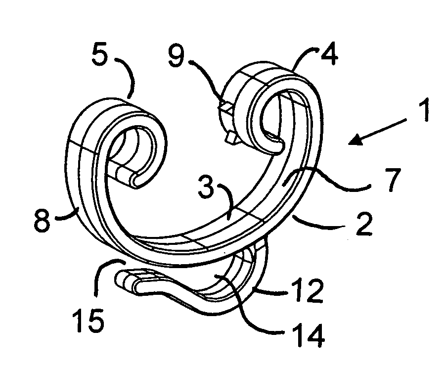
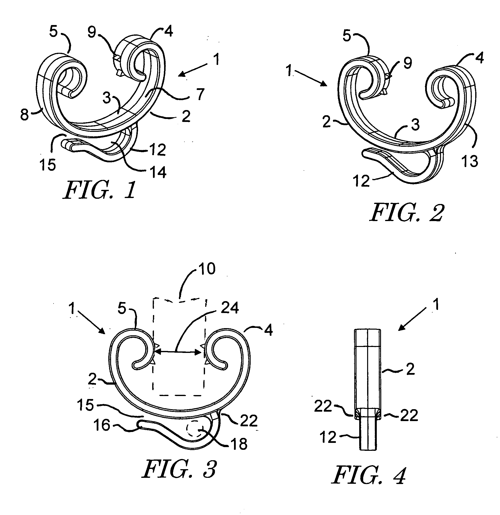
[0015] The present preferred eaves clip 1 shown in the figures has an elongated ribbon shaped body 2. This body has an intermediate curved section or portion 3 extending between curved ends 4 and 5. The curved ends 4 and 5 are generally spiral shaped and integrally formed with the intermediate section 3. The curved ends 4 and 5 curve inward around an arc greater than 180°. The ends 4, 5 and intermediate portion 3 have an inside surface 7 and an outside surface 8. I prefer to provide teeth 9 on the outside surface of each curved end 4 and 5. As can be seen in FIG. 3, these teeth can bite into the eaves 10 or other object shown in dotted line to which the eaves clip is attached. The region where hooks 9 are provided could be flat rather than curved. This flat area would rest against the surface of the eaves and may or may not have teeth. A hook 12 extends from the outside surface of the intermediate portion 3. This hook is configured so that the hook and intermediate portion define a ...


PUM


Abstract

A clip for hanging decorative lights from the eaves of a house has an elongated C-shaped body. This body has an intermediate curved section extending between two ends that curve inwardly. A hook is attached to the outside surface of the intermediate curved section. The elongated body is made of a flexible plastic having a memory such that the curved ends may be moved away from one another by a force acting on at least one of the distal ends. When the force is removed the memory will cause the distal ends of the clip to move together. The inward curvature enables the curved ends to unravel to some extent. The combination of the unraveling of the ends and the flexing of the curved intermediate portion enables this clip to fit onto eaves ranging in width from ⅝ inch to over two inches without breaking.

Description

FIELD OF THE INVENTION [0001] The invention relates to hooks and clips used for hanging strings of decorative lights and like objects from eaves of a house or other building. BACKGROUND OF THE INVENTION [0002] During holiday seasons many homeowners place decorations on and around their houses. One popular way to decorate a house is to attach strings of decorative lights to the edge of the roof or eaves of the house. It has been known to attach decorative light strings by using staples or hooks which are attached to the eaves. This type of attachment creates holes in the wood when the staples or hooks are removed. [0003] Another type of eaves hook involves a generally U-shaped clip which fits over the eaves. One example of such a clip is disclosed in U.S. Pat. No. 3,883,926 to Reynolds. This clip has a flat base containing a hole in which the socket of a decorative light is held. Two arms extend upward from opposite edges of the base and are directed inward toward one another. At the...

Claims


Application Information

Patent Timeline
Patent Type & Authority Applications(United States)
IPC IPC(8): F16L3/24
CPCF16L3/127F16L3/13
Inventor ADAMS, WILLIAM E.
Owner ADAMS MFG
Why Eureka
Try Eureka