[0018]Thus, there are many types of thermochromic and
electrochromic devices made of alternating
layers of (or regions of) liquids, solids, gases, polymers, plastics, metals, and other material. In particular, making these devices or “filters” flexible, light, robust (e.g. resistant to shear, flexion, tearing, creasing, heat, and
humidity), improves them by making them easy and inexpensive to transport and install. Making them so that they can be sized (e.g.
cut to any size and sealed) reduces manufacturing, transport, and installation costs. Making them so that they are light, robust, and easily adhered to surfaces makes them both easy and inexpensive to install, and increases the market for retrofit applications.
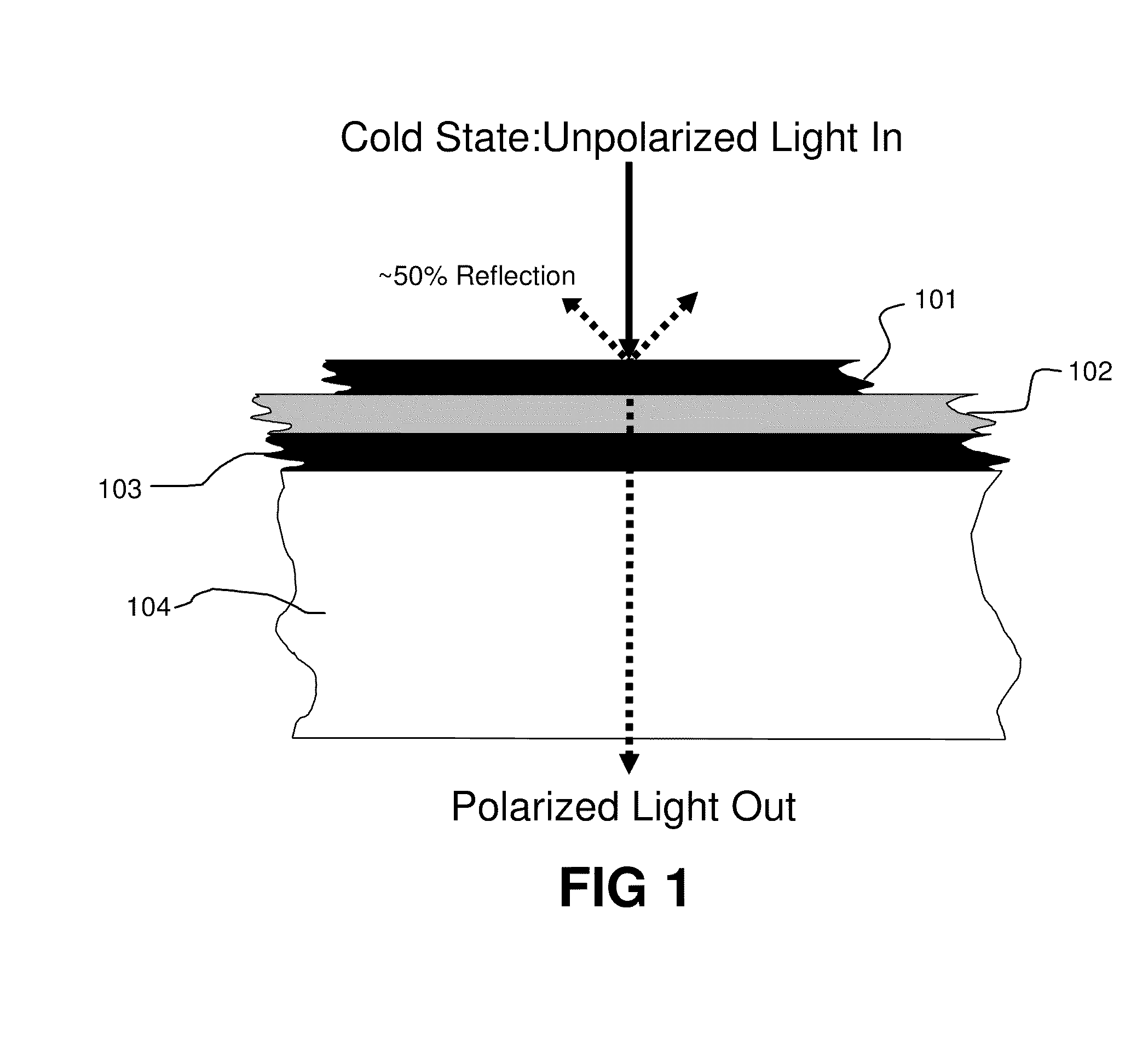
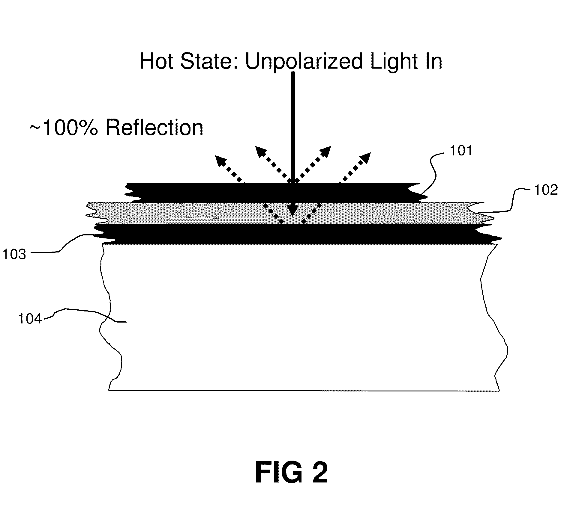
[0021]Devices utilizing the temperature dependent index of
refraction of liquid crystals and other materials, especially as components of distributed Bragg reflectors and polarizers based on similar effects, have been previously described. The technology disclosed herein is directed to making such devices—as well as thermochromic and
electrochromic devices—flexible, robust, light, and sizable by combining these components into one or more flexible
layers, substrates, or similar organizations, with robust and / or flexible connections between them.
[0027]This application describes various methods for fabricating, sizing, transporting, and installing thermochromic optical and near
infrared filters (e.g. thermochromic window filters, including thermoreflective window filters). Thermochromic filters can be fashioned in a variety of formats, including rigid structures that can be laminated to a sheet of glass. However, for use in industries such as glass panel manufacturing, the ideal thermochromic filter should be robust, light, flexible, able to be
cut to any size and shape, and easily transported and installed. This makes it possible for example to manufacture the filters in one standard size in a central location (e.g., a large sheet or roll), to trim them to an appropriate size before or after shipping them safely and inexpensively to other locations, and to conveniently install them in both pre-fit and retro-fit applications.
[0028]It is possible to construct alignment
layers in flexible polarizers made of materials such as polymers, such as 3M DRPF, through “
scratching,”“
rubbing,” or micro / nano-patterning. Alternatively, a layer may be placed on the inside of the “
bottle” that is a superior surface for alignment layers, having properties such as a desired pre-tilt angle. In electrochromic applications, the thickness of the alignment layer may be critical since it is between the conductive layer and the liquid
crystal and thus may affect the switching speed of a display. However, in thermochromic and thermoreflective filters, the conductive layer may be omitted. It is thus possible to make the “
bottle” using the “inside” surfaces of flexible polarizers as the alignment layers, and the resulting
bottle will be robust, flexible, and light. Similarly, it is possible to make bottles and alignment layers out of polymer sheets that are not polarizers. If a separate optional alignment layer is added, the alignment layer material may be chosen to maximize the
chemical stability of the LC, and as a barrier between the LC and other layers.
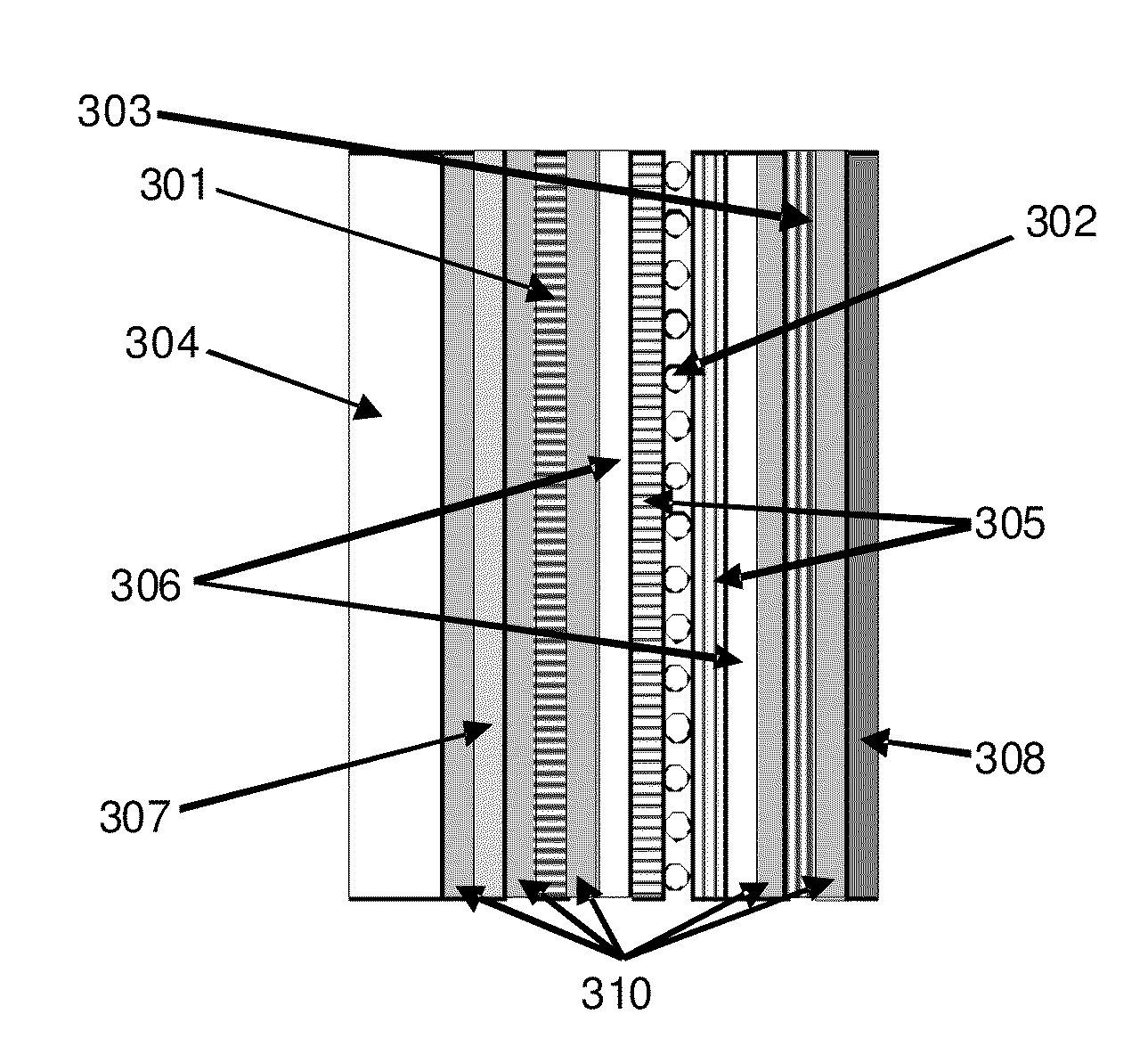
[0029]Spacing of the LC layer in LC devices is often created by utilizing glass or plastic “spacers” (of various shapes and sizes, but most often spherical beads) held between two rigid “plates” covered in layers of conductive material. In electrochromic liquid crystal (LC) devices, the spacing between the conductive layers is often critical for two reasons. The first is to provide a good
electric field across the device. The second is that
high contrast ratios are desirable in electrochromic displays, and the highest contrast ratios are achieved at certain thickness of a given LC fluid, the so-called first and second minima. However, because in thermochromic
liquid crystal devices the
electric field may be omitted, and the contrast ratios desired are relatively low, the thickness of the LC may be significantly less critical; in fact, the only critical
determinant of the spacing or thickness may be ensuring that there is enough liquid crystal in the bottle in any one place such that it is thick enough to act as a wave block at the frequencies of light of interest. However, minimizing the amount, and therefore the cost, of liquid crystal used in such filters is also a goal of many possible spacing designs. Such designs may include using glass spacers to ensure adequate thickness and melting or adhering slightly larger polymer spacers into the sides of the bottle under pressure to limit the maximum volume of LC that can occupy the bottle.
[0031]The methods of manufacturing flexible bottles, gaskets and plugs, spacers and tensioners, alignment layers, gaskets, and other structures for
polarizer-based thermochromic devices, as well as
cutting and resealing, as disclosed herein also apply to the manufacture transport, of
polarizer-free thermochromic devices. This is similarly true for those methods for transporting, sizing, and installing such filters. Such integrated thermochromic
liquid crystal devices are easier and less expensive to manufacture, and are easier to transport and install than such a filter manufactured using more traditional LC display methods.

