Spherical universal coupling

a universal coupling and coupling technology, applied in the direction of couplings, yielding couplings, rotary machine parts, etc., can solve the problems of limited rotational speed of joints, and high cost of joints, so as to reduce sliding action and associated heat and wear, and precise ball-slot grinding

Inactive Publication Date: 2009-12-15
TORVEC INC
View PDF34 Cites 11 Cited by
  • Summary
  • Abstract
  • Description
  • Claims
  • Application Information

AI Technical Summary

Benefits of technology

[0012]A pair of spherical gears connects the intersecting shafts of a CV-joint. One gear has internal teeth, and the other has external teeth. The gear design is based on pitch circles that are great circles on theoretical pitch spheres that are concentric and have identical radii. The internal teeth are either conically or spherically shaped, while the external tooth faces are cylindrical with tangential flat extensions. The spherical gears are shown on half-shafts. The preferred embodiments have six teeth on each gear, and one preferred embodiment also uses balls for the internal teeth. The gears, while rotating at high speeds under load, can intersect throughout a continuous maximum range of 60° or more in any direction. The spherical gear design provides a practical commercial CV-joint that is lighter but stronger than existing joints, while being easier and less expensive to manufacture. A half-shaft using the spherical gear design is also disclosed.
[0016]In one embodiment, the invention's spherical-gear CV-joints are incorporated in an automotive half-shaft along with a small plunge adaptor on the shaft end of one of the joints. In another half-shaft embodiment, the plunge adaptor is incorporated as part of the mounting for the ball-tooth gears of one of the couplings. In comparison with existing commercial half-shaft assemblies, both embodiments (a) significantly reduce sliding action and the associated heat and wear caused by such sliding, (b) eliminate the need to grind very difficult internal curvilinear or skewed grooves in the CV-housing cups, (c) eliminate the need for separate ball retainers with their difficult internal and external spherical grinds as well as precise ball-slot grinding, and (d) thus also eliminate the need for cam-action slot modifications to position a separate ball retainer properly. The intermediary function of the ball retainer and ball set of present commercial CV-joints, used as a motion-transmission link between female slot sets, is replaced by a direct-driven male / female geometry with favorable rolling action between elements.
[0017]Further, each of the invention's half-shaft embodiments uses spherical-gear elements of common design in both the non-plunging outer and the plunging inner CV-joint subassemblies, reducing inventory, production, and assembly complexity and costs.
[0018]The constant velocity joints disclosed herein transmit rotation from a driving shaft to a driven shaft while the shafts intersect at varying angle, e.g., for transmitting driving torque between an automotive engine shaft and a vehicle's drive wheels, or for reducing tangential loads on engine pistons by connecting the piston rods with the output shaft of an automotive engine, etc.

Problems solved by technology

However, such universal and CV-joints are quite complex and relatively difficult to lubricate, and the design and manufacture of such joint components is widely recognized as a very specialized and esoteric art of critical importance to the worldwide automotive industry.
While this universal joint art is very well developed, the joints are expensive, including many parts that are difficult and expensive to manufacture due to large surface areas that must be ground with extreme accuracy (e.g., ±0.0002″ / 0.005 mm).
Such joints are limited in regard to the rotational speeds that they can transmit and, more particularly, in regard to the size of the angles over which they can operate efficiently.
With respect to motion limitation in the existing commercial CV-joint designs, the funnel angle (or combined inner and outer cam angles) of Rzeppa meridional slots needs to be higher than 15° to avoid ball-jamming friction, and thus, respective inner and outer ball-guide slots converge and diverge rather rapidly, limiting the total angular range that can be accommodated in a reasonably-sized CV-joint assembly package.
Unfortunately, the spherical gearing disclosed in U.S. Pat. No. 5,613,914 is fairly complex, difficult to manufacture, and lacks the practicality required for commercial CV-joint use.
Each of these joints is complex and expensive to manufacture.

Method used


Image

  • Spherical universal coupling
  • Spherical universal coupling
  • Spherical universal coupling

Examples


Embodiment Construction

Spherical Gear Design

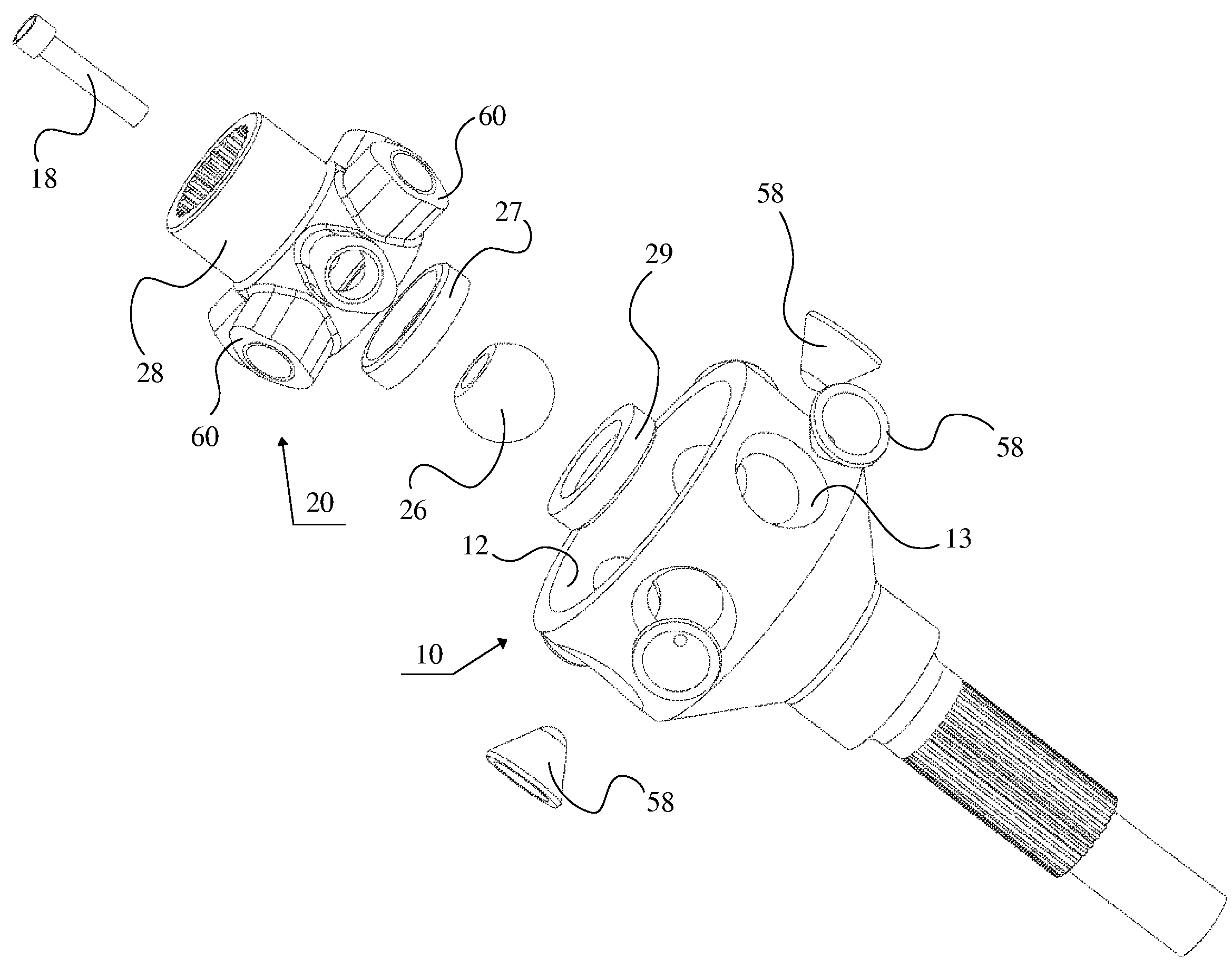
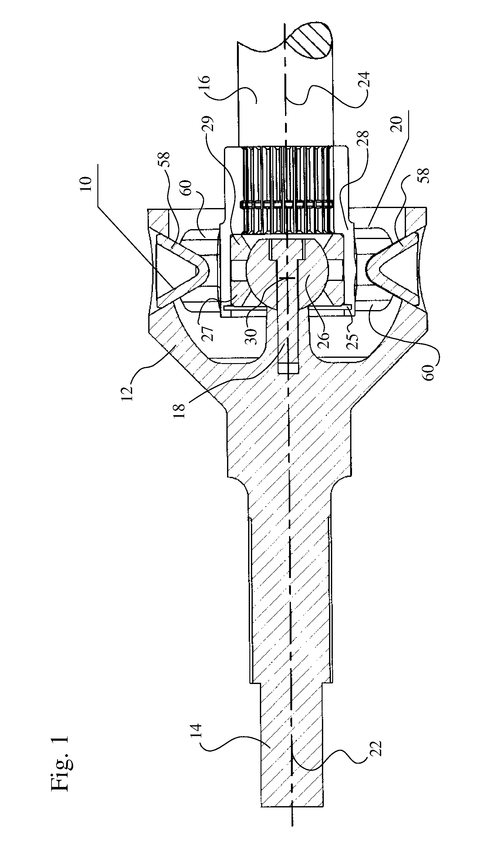
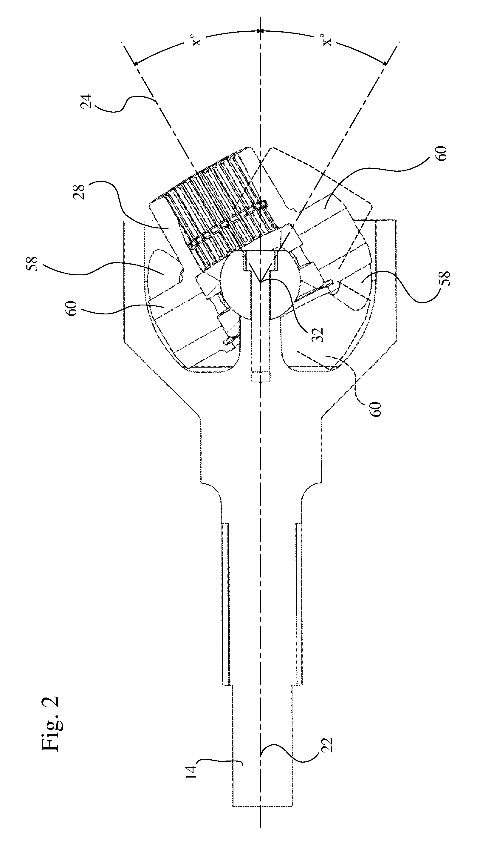
[0047]FIG. 1 and FIG. 2 illustrate a constant-velocity universal joint using spherical gears for interconnecting a pair of rotating shafts. FIG. 1 is a schematic and partially cross sectional view of an exterior gear 10 (with internal teeth 58) fixed within a cup-like support 12 having one end fixed to a first shaft 14. A mating interior gear 20 (with external teeth 60) is fixed for rotation to a second shaft 16. In FIG. 1, shafts 14 and 16 are shown with their respective axes 22, 24 positioned in 180° alignment. Axes 22, 24 are also the respective axes of mating spherical gears 10, 20.

[0048]A spherical bearing maintains the mating gears 10 and 20 in proper meshing relationship. In this embodiment, this spherical bearing includes (a) an interior member, preferably a centering ball 26, fixed to the base of cup-like support 12 by a bolt 18, and (b) an exterior member in the form of a hub 28 formed on the interior of gear 20. The exterior member includes two spheri...


PUM


Abstract

A pair of spherical gears connects the intersecting shafts of a CV-joint. One gear has internal teeth, and the other has external teeth. The gear design is based on pitch circles that are great circles on theoretical pitch spheres that are concentric and have identical radii. The internal teeth are either conically or spherically shaped, while the external tooth faces are cylindrical with tangential flat extensions. The spherical gears are shown on half-shafts. The preferred embodiments have six teeth on each gear, and one preferred embodiment also uses balls for the internal teeth. The gears, while rotating at high speeds under load, can intersect throughout a continuous maximum range of 60° or more in any direction.

Description

REFERENCE TO RELATED APPLICATIONS[0001]This is a continuation-in-part patent application of copending application Ser. No. 11 / 553,736, filed Oct. 27, 2006, entitled “SPHERICAL UNIVERSAL COUPLING”. The aforementioned application is hereby incorporated herein by reference.BACKGROUND OF THE INVENTION[0002]1. Field of the Invention[0003]The invention relates to universal couplings and automotive half-shafts, and more particularly, to constant-velocity universal joints for directly connecting two shafts in a manner that transmits rotation from the driving shaft to the driven shaft while, at the same time, permitting the angle of intersection between the axes of the shafts to be varied away from 180° alignment in any direction over a relatively wide and continuous range of angles (e.g., 60° or more).[0004]2. Description of Related Art[0005]There are well-known, non-gear means for transmitting rotary motion between shafts experiencing angular change. Perhaps the best known of such devices ...

Claims


Application Information

Patent Timeline
Patent Type & Authority Patents(United States)
IPC IPC(8): F16D3/18
CPCF16D3/185F16D3/2057Y10S464/904F16D3/16F16D3/221F16D3/227F16D3/00
Inventor GLEASMAN, KEITH E.SUWIJN, PAUL W.
Owner TORVEC INC
Why Eureka
Try Eureka