Ferrule assembly for optical fibres

a technology of optical fibres and assemblies, applied in the field of ferrule assembly for optical fibres, can solve the problems of time-consuming and difficult manufacturing of these components, and achieve the effect of convenient and less expensive manufacturing

Inactive Publication Date: 2006-12-12
FRAMATOME CONNECTORS INT SA
View PDF11 Cites 13 Cited by
  • Summary
  • Abstract
  • Description
  • Claims
  • Application Information

AI Technical Summary

Benefits of technology

[0004]It is an object of the invention to provide a ferrule assembly and a manufacturing method for a high-density ferrule plate of such an assembly that is easier and less expensive to manufacture while keeping the required accuracy in holding the optical fibres.
[0007]In an embodiment of the invention the ferrule plate is a ceramic ferrule plate or, alternatively it is made of a material having the same thermal expansion coefficient as the board that embeds the device or the substrate material of the embedded device. Ceramic ferrule plates are advantageous in that such plates have a low to ultra-low thermal expansion coefficient thereby reducing misalignment of the contained optical fibres with a device as a result of temperature variations. In the alternative embodiment the equal thermal expansion of both the board and the ferrule plate prevents misalignment as well.
[0008]In an embodiment of the invention the ferrule assembly comprises three alignment elements, positioned to control alignment from the centre of said two-dimensional array of through-holes. Such an alignment configuration is especially advantageous for large arrays, e.g. exceeding 8×8 to control mismatches between the optical fibres and e.g. an optical chip embedded in a circuit board as a result of differences in the thermal expansion coefficient. The alignment configuration thus prevents considerable distortions of the optical signal.
[0009]In an embodiment of the invention the assembly comprises a ferrule holder with at least one cavity for receiving said optical fibres. Such a cavity may e.g. be used to hold the ribbon cables comprising the optical fibres. Preferably the assembly has an integrated ferrule plate and ferrule holder. In such an assembly the ferrule holder may support the ferrule plate in close proximity to e.g. an embedded optical chip such that optical components as optical lenses can be omitted for transmission of the optical signals between the optical chip and the optical fibres. Alternatively the ferrule holder and the ferrule plate are modular parts of the assembly facilitating manufacturing of the parts.
[0015]This method of manufacturing is more simple and less time-consuming than the prior art etching method and additionally more accurate than laser drilling. The moulding method allows the protrusions of the mould to shape the through-holes in the ferrule plate with octagonal edges and preferably also in a tapered fashion in the axial direction.

Problems solved by technology

The fibre optic component of the prior art is disadvantageous in that manufacturing of these components is difficult and time-consuming.

Method used


Image

  • Ferrule assembly for optical fibres
  • Ferrule assembly for optical fibres
  • Ferrule assembly for optical fibres

Examples


Embodiment Construction

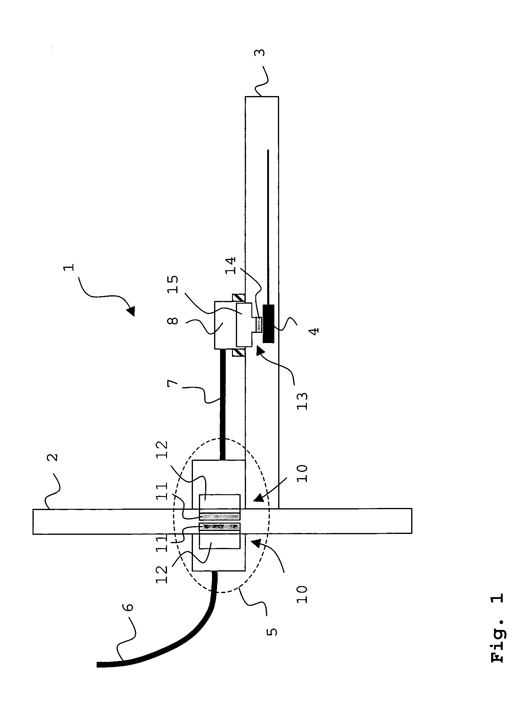
[0029]In FIG. 1 an optical system 1 is shown comprising a backpanel 2 and a system card 3 with an embedded device 4. The embedded device 4 may e.g. be an active optical or electro-optical component, such as a combination of a vertical cavity surface emitting laser (VCSEL) and a sensor, or a passive component such as a mirror or one or more embedded optical waveguides. A connector assembly 5 optically connects a plurality of optical cables 6 via the off-board optical cables 7 to a surface mounted board connector 8. The optical cables 6, 7 may comprise a plurality of ribbon cables (shown in FIG. 5) each of said cables comprising a plurality of optical fibres (shown in FIG. 5). Optical signals may be transferred over those optical fibres to or from the device 4. The device 4 is embedded in the system card or PCB 3 and connected to other components (not shown) via waveguide 9.

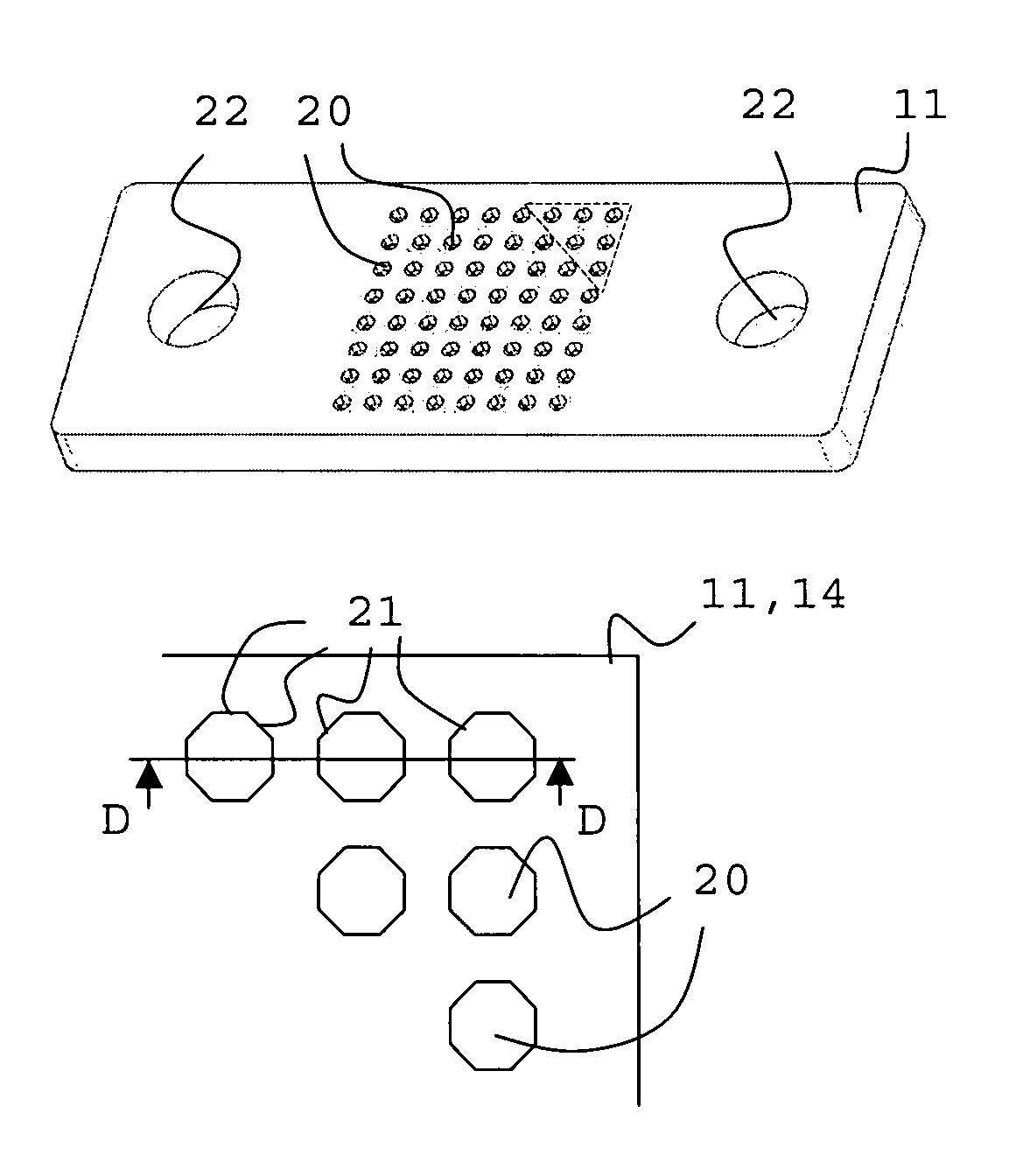
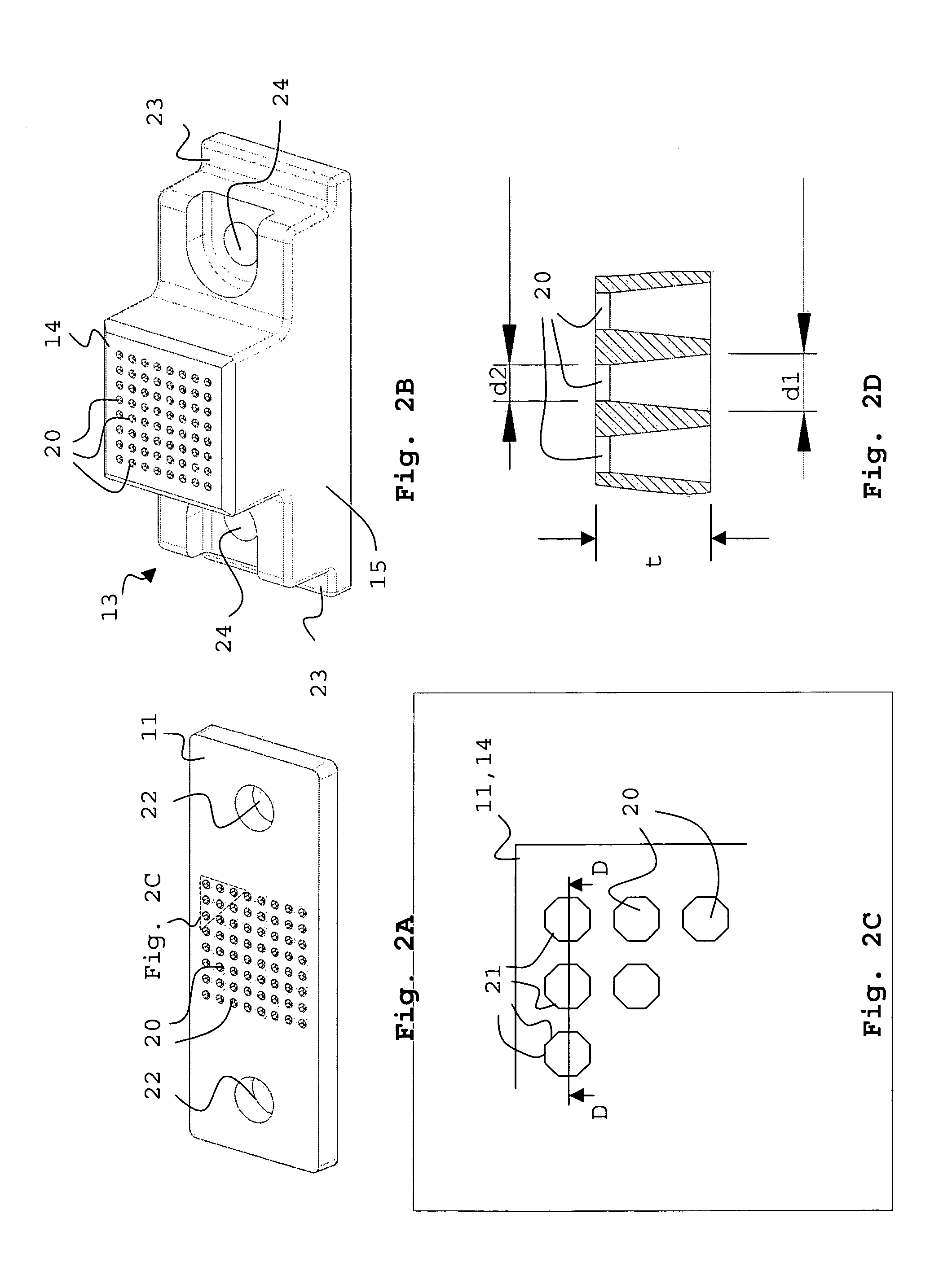
[0030]At the backpanel 2 the connector assembly 5 comprises ferrule assemblies each having a ferrule plate 11 an...


PUM


Abstract

The invention relates to a ferrule assembly for optical fibres comprising a high-density ferrule plate with a two-dimensional array of through-holes for said optical fibres. The holes of the ferrule plate comprise substantially straight edges adapted to substantially contain said optical fibres. The invention further relates to a method for manufacturing a high-density ferrule plate, a mould for die casting such a high-density ferrule plate and a method for manufacturing such a mould.

Description

FIELD OF THE INVENTION[0001]The invention relates to a ferrule assembly for optical fibres comprising a high-density ferrule plate with a two-dimensional array of through-holes for said optical fibres.BACKGROUND OF THE INVENTION[0002]WO 03 / 003064 discloses a multi-piece fibre optic component to accurately hold an optical fibre within a commercial type connector. The component comprises a first high precision slice with multiple holes and a second high precision slice with multiple holes. The holes of both pieces have a substantially circular or oval cross section and are aligned by alignment openings such that the holes are offset relative to each other to define an opening having an area less than that of the openings of either slice. The slices preferably are stacks of silicon wafers and the holes are preferably manufactured by anisotropic etching.[0003]The fibre optic component of the prior art is disadvantageous in that manufacturing of these components is difficult and time-con...

Claims


Application Information

Patent Timeline
Patent Type & Authority Patents(United States)
IPC IPC(8): G02B6/00G02B6/40G02B6/36G02B6/38
CPCG02B6/3885G02B6/3897G02B6/3644G02B6/3664G02B6/3692
Inventor LANGE, LUDWIG GERARDUS MARTINUS ANTONIUSVAN DER STEEN, HENRIKUS PETRUS GIJSBERTUS
Owner FRAMATOME CONNECTORS INT SA
Why Eureka
Try Eureka