
Self-loading peristaltic pump for extracorporeal blood circuit

a peristaltic pump and extracorporeal technology, applied in the field of peristaltic pumps, can solve the problems of difficult operation, mechanical complexity of conventional automatic tube loading mechanism, and relatively long pump setup tim

Inactive Publication Date: 2006-03-28
GAMBRO LUNDIA AB
View PDF13 Cites 42 Cited by
  • Summary
  • Abstract
  • Description
  • Claims
  • Application Information

AI Technical Summary

Problems solved by technology

Conventional automatic tube loading mechanisms tend to be mechanically complex, to have tabs and other rotating protrusions that can catch and pinch fingers of operators, have a relatively long pump setup time and to be difficult to operate.

Method used


Image

  • Self-loading peristaltic pump for extracorporeal blood circuit
  • Self-loading peristaltic pump for extracorporeal blood circuit
  • Self-loading peristaltic pump for extracorporeal blood circuit

Examples


Embodiment Construction

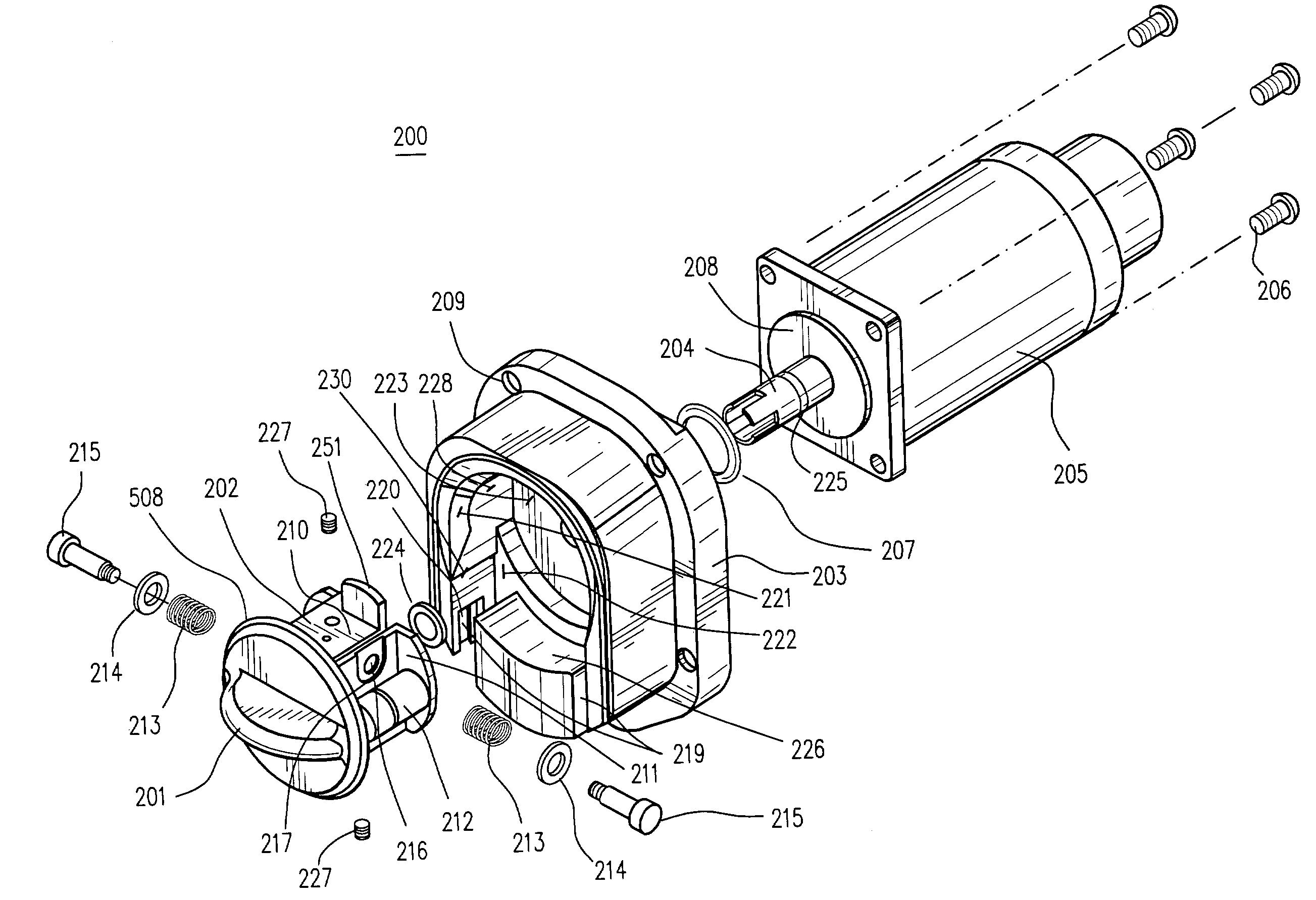
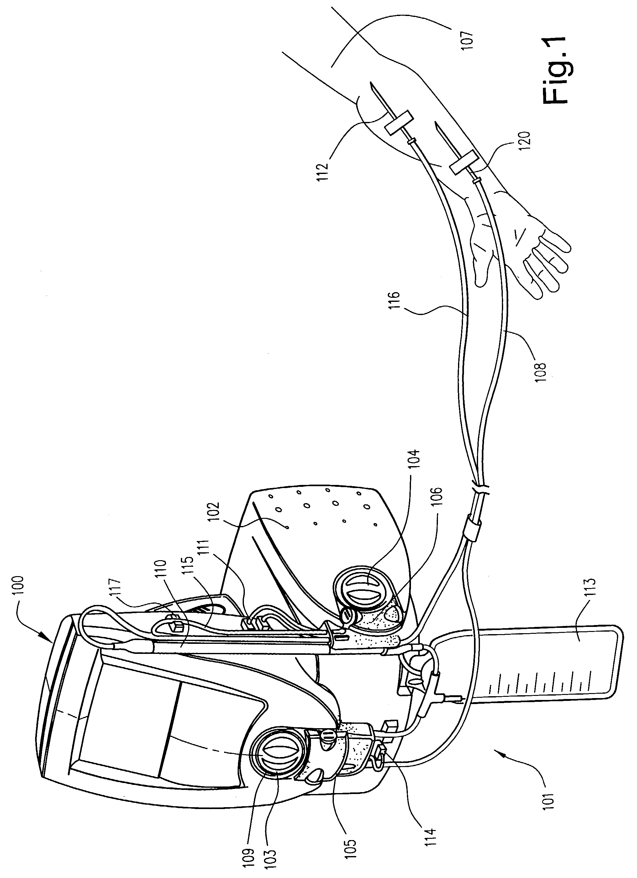
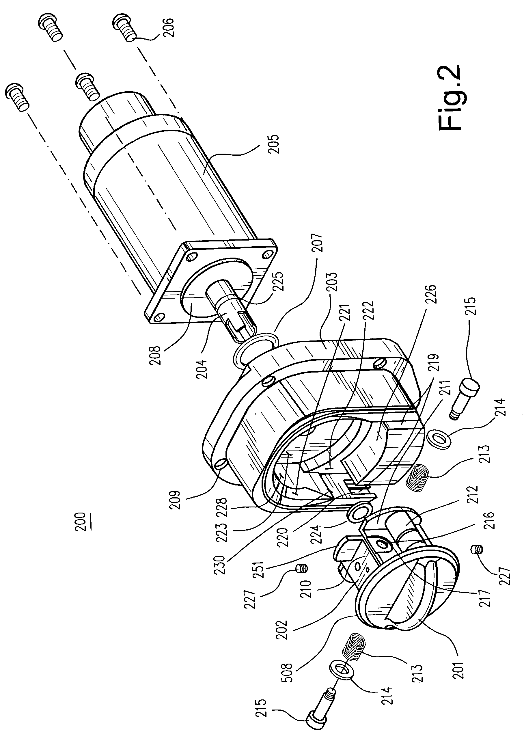
[0015]FIG. 1 shows an ultrafiltration device 100 for the removal of isotonic fluid from the blood of patients 107 suffering from fluid overload. The device 100 includes a disposable blood circuit 101 that is realeasably mounted on a peristaltic pump console 102. The console includes a first peristaltic pump 103 that controls a rate at which blood is withdrawn from the patient 107, and a second peristaltic pump 104 that controls a rate of filtrate, e.g. isotonic fluid, flowing from a blood filter 110 of the circuit. The circuit 101 further includes a pair of circuit cartridges 105, 106 that are removably attached to the pumps and their console. The major blood circuit components comprise the tubing 108, 109, 115, 116; cartridges 105, 106; filter 110; pressure sensors 111, 114; blood leak detector 117 and filtrate collection bag 113. The blood circuit may be disposed of after one ultrafiltration use.

[0016]Blood is withdrawn from the patient 107 through a peripheral access cannula 120 ...


PUM


Abstract

A peristaltic pump is disclosed having pump motor with a rotating motor shaft and a shaft axis; a peristaltic pump head rotatably mounted on the motor shaft; a raceway having a semi-circular track arranged around the pump head and coaxial with the shaft axis, wherein the track has a beveled edge at an entrance to the raceway to receive a tube loop being loaded into the pump; the pump head includes at least one roller orbiting the raceway and compressing the tube loop against said raceway, and a cartridge to which the tube loop is attached and mountable on the raceway.

Description

FIELD OF INVENTION[0001]The present invention relates to the field of peristaltic pumps and more particularly to the field of peristaltic pumps that are used for extracorporeal blood treatment and analysis.BACKGROUND OF THE INVENTION[0002]A peristaltic pump moves blood, filtrate and other liquids through tubing of an extracorpeal blood circuit. One or more peristaltic pumps may be arranged in a pump console which usually includes a pump controller and user interface. The blood circuit is releasably mounted onto the pump console and the tubing of the circuit is loaded in the peristaltic pumps. The rotating pumps drive blood and other liquids through the tubing of the blood circuit.[0003]An automatic loading mechanism for loading the tubing onto the pumps is desirable to ease the task of inserting the tubing into the pump and to avoid pinching the fingers of the operator loading the tubing. An exemplary automatic tubing loading mechanism, described in U.S. Pat. No. 4,861,242, has a ro...

Claims


Application Information

Patent Timeline
Patent Type & Authority Patents(United States)
IPC IPC(8): F04B43/12
CPCF04B43/1253
Inventor O'MAHONY, JOHN J.BEHAN, SONNY
Owner GAMBRO LUNDIA AB
Learn More