Coordinated engine torque control

a torque control and engine technology, applied in the field of engine, can solve the problems of not being able to provide as rapid a response to control signals, traditional engine control systems, and not being able to control the torque output of engines as accurately as desired

Active Publication Date: 2006-04-04
GM GLOBAL TECH OPERATIONS LLC
View PDF5 Cites 101 Cited by
  • Summary
  • Abstract
  • Description
  • Claims
  • Application Information

AI Technical Summary

Benefits of technology

The present invention provides a system for controlling the operation of an engine by regulating the flow of air and the output of torque. The system uses a throttle and a device to control the engine's torque output. The system includes three modules: a first module determines the throttle area based on the desired pressure and air flow, a second module determines the device set-point based on the desired air per cylinder and engine speed, and a third module generates the throttle control signal to control the throttle and the device control signal to control the device. This system allows for precise control of engine performance and efficiency.

Problems solved by technology

The technical problem addressed in this patent is the inaccuracy and slow response time of traditional engine control systems in controlling engine torque output and the lack of coordination among various devices that affect engine torque output.

Method used


Image

  • Coordinated engine torque control
  • Coordinated engine torque control
  • Coordinated engine torque control

Examples


Embodiment Construction

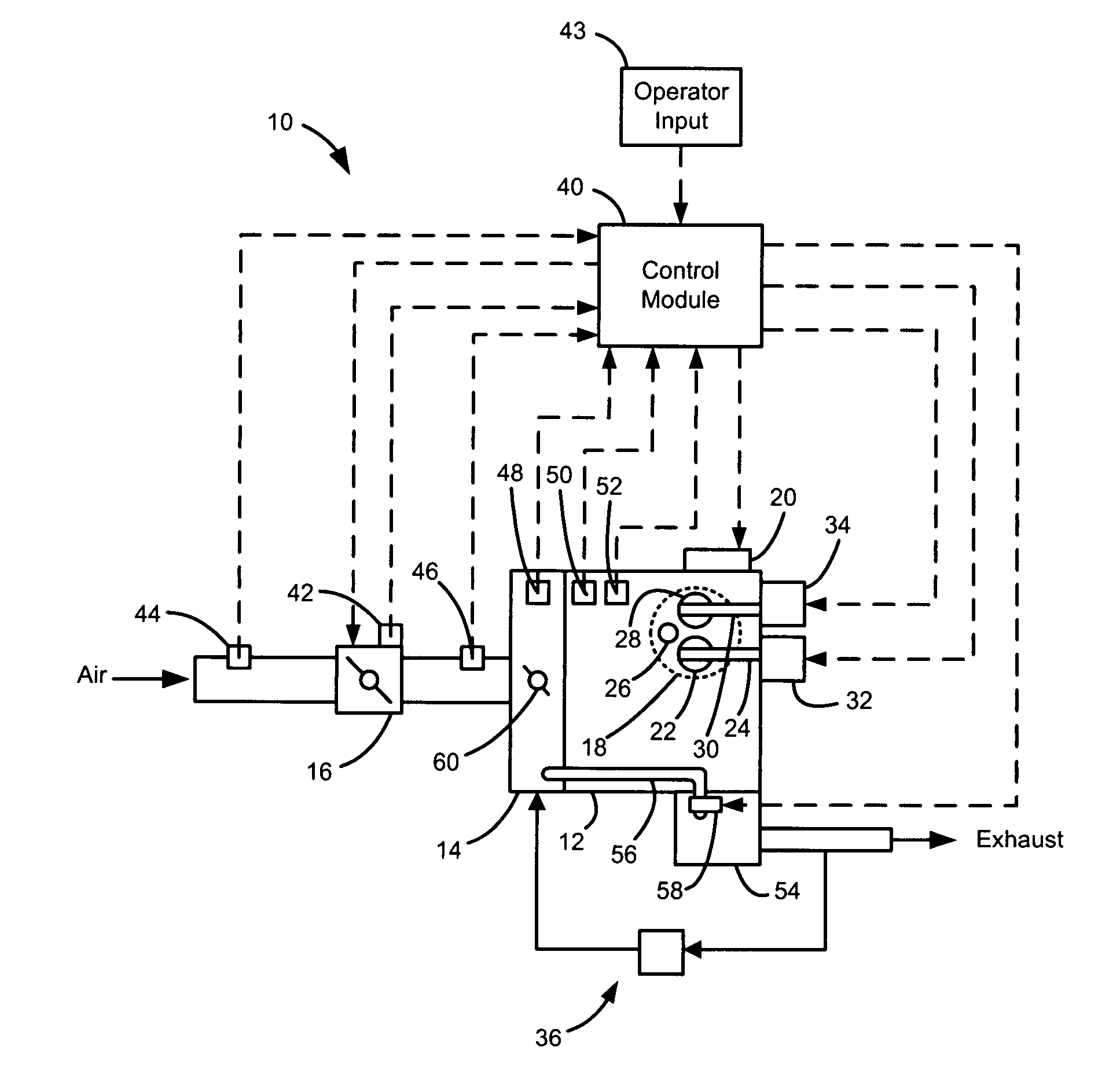
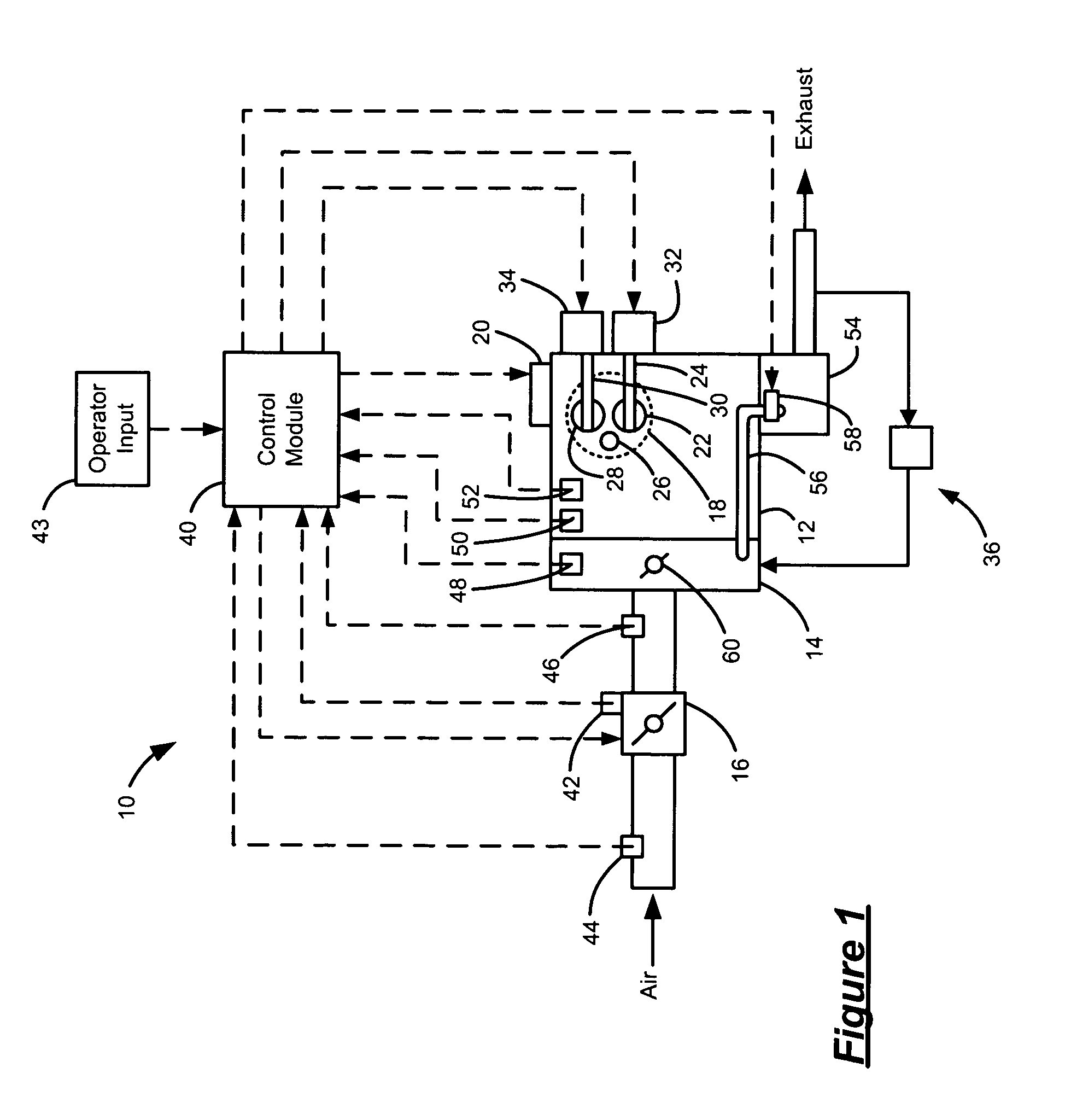
[0019]The following description of the preferred embodiment is merely exemplary in nature and is in no way intended to limit the invention, its application, or uses. For purposes of clarity, the same reference numbers will be used in the drawings to identify similar elements. As used herein, the term module refers to an application specific integrated circuit (ASIC), an electronic circuit, a processor (shared, dedicated, or group) and memory that execute one or more software or firmware programs, a combinational logic circuit, or other suitable components that provide the described functionality.

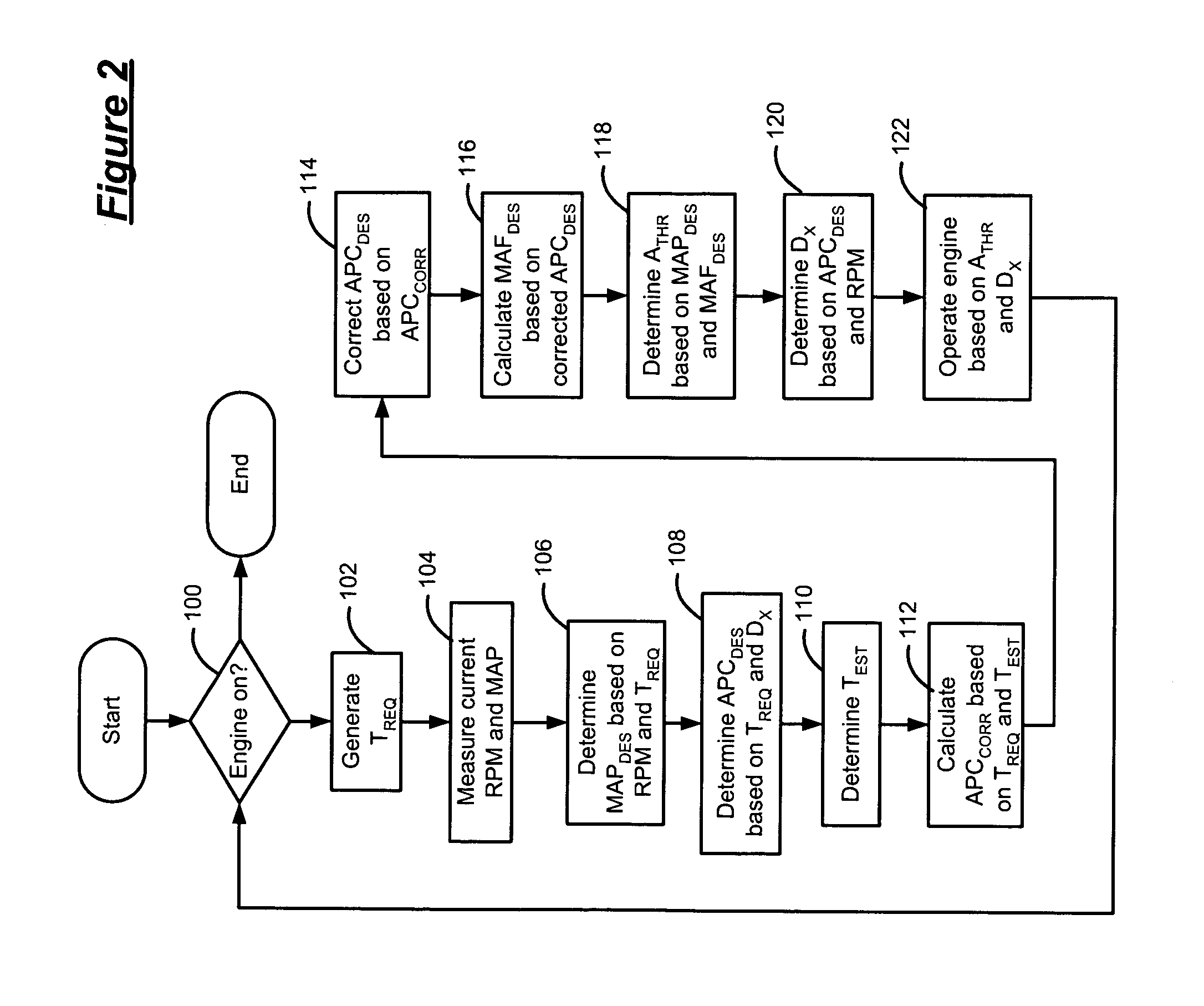
[0020]Referring now to FIG. 1, an engine system 10 includes an engine 12 that combusts an air and fuel mixture to produce drive torque. Air is drawn into an intake manifold 14 through a throttle 16. The throttle 16 regulates mass air flow into the intake manifold 14. Air within the intake manifold 14 is distributed into cylinders 18. Although a single cylinder 18 is illustrated, it can be ap...


PUM


Abstract

A torque control system for regulating operation of an engine includes a throttle that regulates air flow into the engine and a device that regulates a torque output of the engine. A first module determines a throttle area based on a desired manifold absolute pressure (MAP) and a desired manifold air flow (MAF) and a second module determines a device set-point based on a desired air per cylinder (APC) and an engine speed. A third module generates a throttle control signal to control the throttle based on the throttle area and generates a device control signal to control the device based on the device set-point.

Description


Claims


Application Information

Patent Timeline
Owner GM GLOBAL TECH OPERATIONS LLC
Why Eureka
Try Eureka