Continuous pressure letdown system

a technology of letdown and continuous pressure, which is applied in the direction of auxillary pretreatment, furnaces, separation processes, etc., can solve the problems of high capital cost and/or relatively low availability, large transient upset conditions, and low availability

Active Publication Date: 2010-06-08
GAS TECH INST
View PDF15 Cites 45 Cited by
  • Summary
  • Abstract
  • Description
  • Claims
  • Application Information

AI Technical Summary

Benefits of technology

[0007]A continuous pressure letdown system connected to a hopper decreases a pressure of a 2-phase (gas and solid) dusty gas stream flowing through the system. The system includes a discharge line for receiving the dusty gas from the hopper, a valve, a cascade nozzle assembly positioned downstream of the discharge line, a purge ring, an inert gas supply connected to the purge ring, an inert gas

Problems solved by technology

An issue with existing gasification technologies is that they generally have high capital costs and/or relatively low availability.
One cause for low availability is that current coal gasification systems operate as batch processes for filtering ash particles from the synthesis gas stream.
While efficient, one concern with using lock hoppers is that they can produce significant transient

Method used


Image

  • Continuous pressure letdown system
  • Continuous pressure letdown system
  • Continuous pressure letdown system

Examples


Embodiment Construction

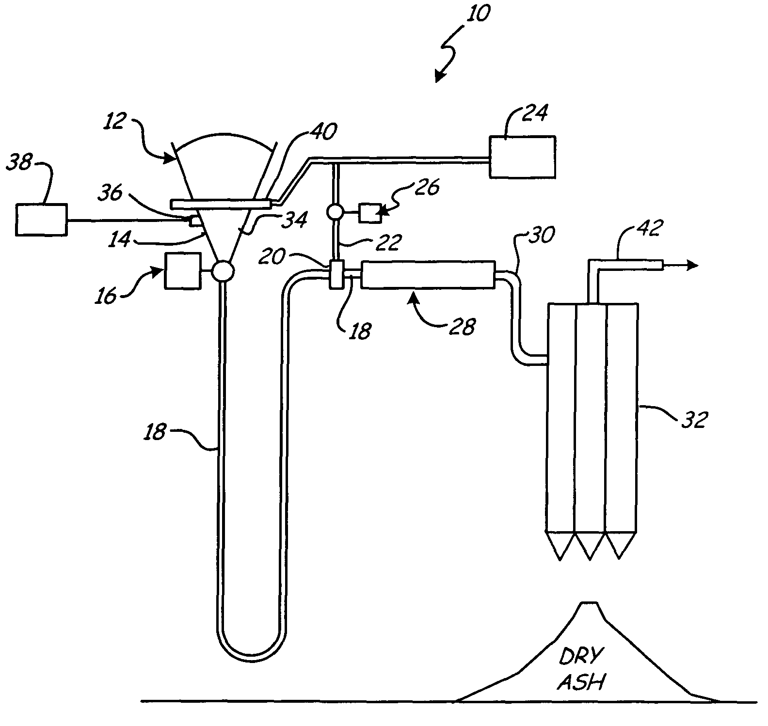
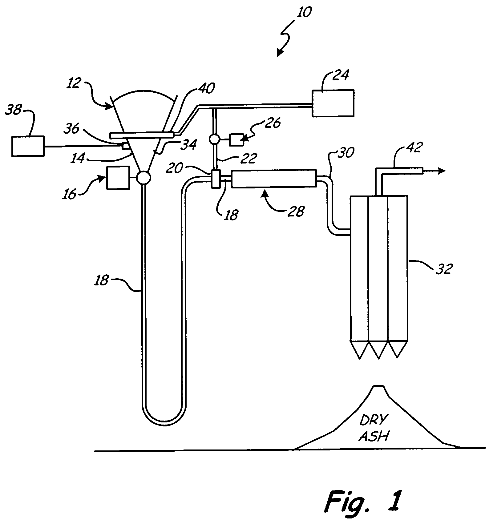
[0015]FIG. 1 shows a schematic view of continuous solids pressure letdown system 10 for use with a gasification system 12. System 10 eliminates the need for cycling lock hoppers, allowing system 10 to operate continuously rather than in a cycling batch mode. The overall size of system 10 is also reduced by eliminating the cycling lock hoppers, which generally require a significant amount of space due to their large size. With continuous operation, (i.e. a cycling frequency of zero) system 10 has a longer expected life, lower maintenance costs, and increased mean time between failures (MTBFs). In addition, by eliminating the need for cycling lock hoppers, the capital equipment costs of system 10 are also significantly reduced. In an exemplary embodiment, system 10 is used in conjunction with a coal gasification system flowing approximately 400 tons of dry ash particles per day.

[0016]As can be seen in FIG. 1, system 10 is connected to a hopper 14 of gasification system 12. Hopper 14 o...


PUM

PropertyMeasurementUnit
Angleaaaaaaaaaa
Lengthaaaaaaaaaa
Percent by volumeaaaaaaaaaa

Abstract

A continuous pressure letdown system connected to a hopper decreases a pressure of a 2-phase (gas and solid) dusty gas stream flowing through the system. The system includes a discharge line for receiving the dusty gas from the hopper, a valve, a cascade nozzle assembly positioned downstream of the discharge line, a purge ring, an inert gas supply connected to the purge ring, an inert gas throttle, and a filter. The valve connects the hopper to the discharge line and controls introduction of the dusty gas stream into the discharge line. The purge ring is connected between the discharge line and the cascade nozzle assembly. The inert gas throttle controls a flow rate of an inert gas into the cascade nozzle assembly. The filter is connected downstream of the cascade nozzle assembly.

Description

STATEMENT REGARDING FEDERALLY SPONSORED RESEARCH OR DEVELOPMENT[0001]This invention was made with the support of the United States Government under Contract No. DE-FC26-04NT42237 awarded by the Department of Energy (DOE). The United States Government has certain rights in the invention.BACKGROUND OF THE INVENTION[0002]The present invention generally relates to advanced coal gasification systems. In particular, the present invention relates to a continuous coal gasification system.[0003]The gasification process involves turning coal or other carbon-containing materials into dusty gas, such as hydrogen and carbon monoxide. Because coal costs less than natural gas and oil, there is a large economic incentive to develop gasification technology. An issue with existing gasification technologies is that they generally have high capital costs and / or relatively low availability. Availability refers to the amount of time the equipment is on-line and making products. One cause for low availabi...

Claims


Application Information

Patent Timeline
IPC IPC(8): B01D46/00
CPCB01D45/12B01D46/2407B01D46/02
Inventor SPROUSE, KENNETH M.MATTHEWS, DAVID R.LANGOWSKI, TERRY
Owner GAS TECH INST
Why Eureka
Try Eureka