Backpressure mechanism of scroll type compressor

a backpressure mechanism and scroll type technology, applied in the direction of liquid fuel engines, machines/engines, rotary piston liquid engines, etc., can solve the problems of reducing the affecting the operation efficiency of the entire backpressure mechanism, so as to improve the structure of the backpressure mechanism and improve the operation efficiency of the compressor. , the effect of improving the operation efficiency

Inactive Publication Date: 2006-04-18
RECHI PRECISION
View PDF13 Cites 41 Cited by
  • Summary
  • Abstract
  • Description
  • Claims
  • Application Information

AI Technical Summary

Benefits of technology

[0009]The primary purpose of the present invention is to provide an improved structure of a backpressure mechanism of a scroll type compressor to upgrade the operation efficiency of the compressor. To achiever the purpose, a recessed seat is provided on the top of a coolant passage located at the center of a fixed scroll and a ring groove is provided on the outer circumference of the recessed seat. Wherein, a floating high-pressure sealing assembly is disposed at the recessed seat, a floating medium-pressure sealing assembly is disposed at the ring groove, and a bypass pore connecting through a compression chamber is provided to the ring groove of the fixed scroll to make sure that both of the high-pressure and the medium-pressure sealing assemblies float and plunge against a separation block located below the high-pressure chamber while the pressure from the compressed coolant enables the fixed scroll to produce an axially compromising and vacuum unloading function to upgrade the operation efficiency of the compressor

Problems solved by technology

Furthermore, the losing of its intended air-tightness function of the sealing device 60 as the compressor is running, the high pressure in the coolant passage 31 escapes to the medium pressure area in the ring groove 32, resulting in abnormal rise of pressure in the medium pressure area and the power to push the fixed scroll becomes significantly higher than that as designed.
Consequently, the operation efficacy of the entire backpressure mechanism is discounted, and the compressor efficiency compromised if not failed.

Method used


Image

  • Backpressure mechanism of scroll type compressor
  • Backpressure mechanism of scroll type compressor
  • Backpressure mechanism of scroll type compressor

Examples


Embodiment Construction

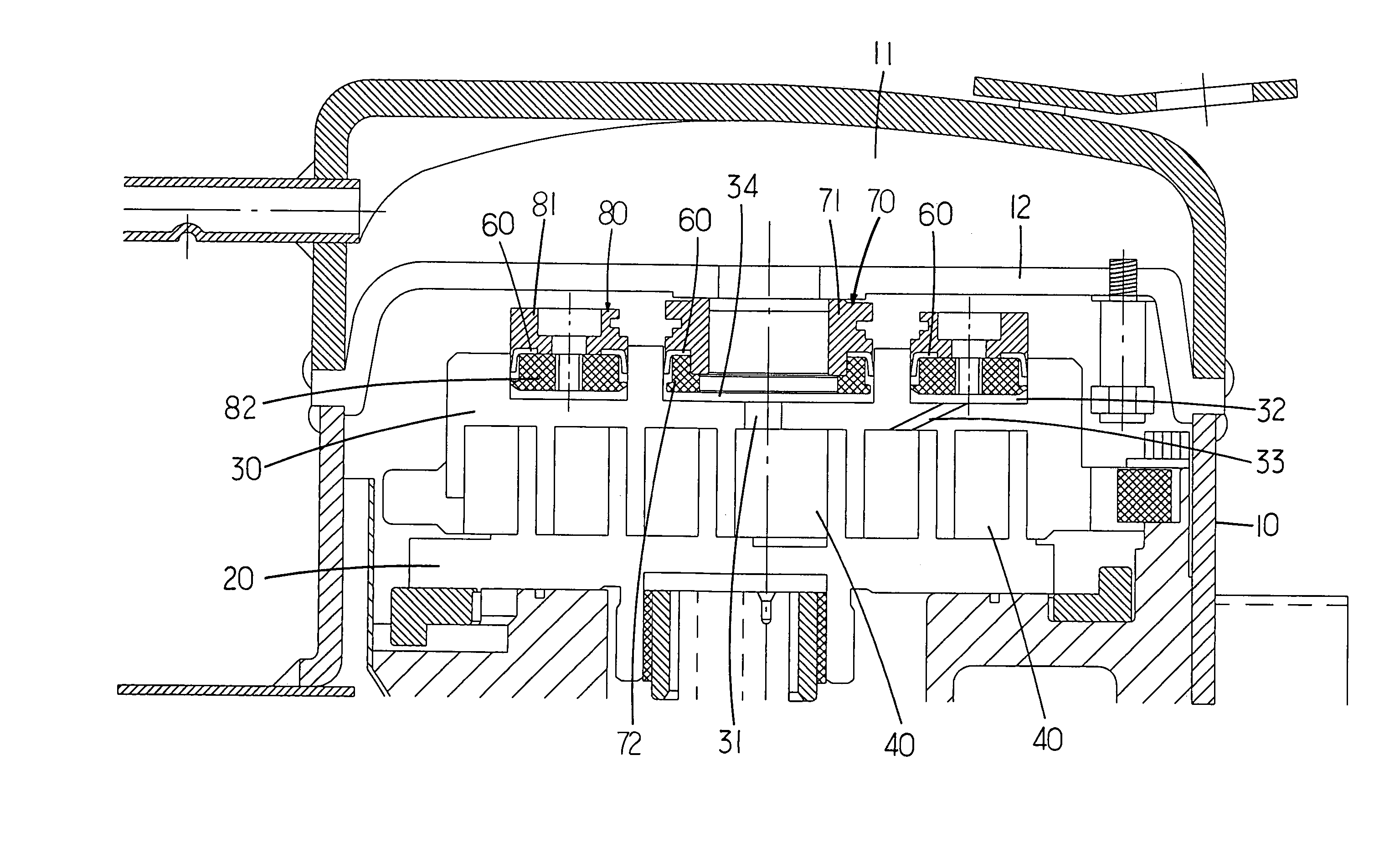
[0020]Referring to FIG. 2(A) for a backpressure mechanism of a scroll type compressor of the present invention, the compressor essentially operates by having an orbiting scroll 20 to revolve around a fixed scroll 30 inside a casing 10 so to cause the pressure gradually and inwardly increasing through multiple compression chambers 40 thus to change the volume of each compress chamber 40 for compressing a coolant. A space in the upper area inside the casing is segregated into a high-pressure chamber 11 by means of an separation block 12, and the compressed coolant passes via a compression chamber 40 located at the center of the fixed scroll 30 through a coolant passage 31 provided in the center of the fixed scroll 30 to enter into the high-pressure chamber 11.

[0021]Wherein, a recessed seat 34 is disposed at the top of the coolant passage 31 at the center of the fixed scroll 30, and a ring groove 32 is provided on the outer circumference of the recessed seat 34. A sealing assembly comp...


PUM


Abstract

A backpressure mechanism for a scroll type compressor to effectively prevent leakage of coolant; a recessed seat being provided at the top of a coolant passage at the center of a fixed scroll; a ring groove being disposed on the outer circumference of the recessed seat; a high-pressure sealing assembly comprised of a high-pressure ring, a sealing device and a high pressure ring seat and a medium-pressure sealing assembly comprised of a medium-pressure ring, a sealing device and a medium-pressure ring seat being respectively provided to the recessed seat and the ring groove; pressure from the compressed coolant causing an axially compromising vacuum unloading function to float the both sealing assemblies.

Description

BACKGROUND OF THE INVENTION[0001](a) Field of the Invention[0002]The present invention is related to an improved structure of a backpressure mechanism of scroll type compressor (STC), and more particularly, to one that prevents compression coolant leakage.[0003](b) Description of the Prior Art[0004]Referring to FIGS. 1(A) and 1(B) of the accompanying drawings for a sectional view of a structure among a casing 10, an orbiting scroll 20 and a fixed scroll of a scroll type compressor generally available in the market, the compressor is provided with a backpressure mechanism of the prior art. The compressor essentially works inside the casing 10 by having the orbiting scroll 20 to revolve around the fixed scroll 30. Multiple compression chambers 40 with increased pressure inwardly chamber by chamber as the orbiting scroll 20 revolves around the fixed scroll 30 thus to change the volume of the compression chamber 40 to compress the coolant.[0005]Wherein, the compressed coolant enters int...

Claims


Application Information

Patent Timeline
Patent Type & Authority Patents(United States)
IPC IPC(8): F04C18/00F03C2/00F01C1/02F01C1/063F03C4/00F04C18/02F04C27/00F04C28/26
CPCF04C18/0215F04C28/265F04C27/005
Inventor CHANG, LUNG-TSAICHIU, CHUNG-PEN
Owner RECHI PRECISION
Why Eureka
Try Eureka