Connector panel mount system

a technology of connecting panel and mounting system, which is applied in the direction of coupling device connection, optical element, instruments, etc., can solve the problems of mounting connecting device, electromagnetic interference has a tendency to migrate directly through the plastic adapter, and additional problems such as the creation of plastic “dus

Inactive Publication Date: 2006-04-18
MOLEX INC
View PDF7 Cites 209 Cited by
  • Summary
  • Abstract
  • Description
  • Claims
  • Application Information

AI Technical Summary

Benefits of technology

[0007]In the exemplary embodiment of the invention, the receptacle or adapter assembly includes a housing mountable in the opening in the panel and including a pair of housing halves secured together at an interface. A first of the housing halves projects from one side of the panel and has a first receptacle for receiving at least one connector. The first housing half is fabricated of plastic material to withstand repeated insertions of the connector with a plastic housing into the receptacle. A second housing half projects from an opposite side of the panel and has a second receptacle for receiving a complementary connecting device for mating with the connector within the adapter assembly. The second housing half is fabricated of metal material to provide EMI protection at the opening in the panel.

Problems solved by technology

Problems are encountered in mounting connecting devices through openings in panels where electromagnetic interference (EMI) is present.
If an adapter in an opening in a panel is fabricated of plastic material which has excellent wear characteristics, such as for allowing repeated mating and unmating of the connectors which typically are made of plastic materials, electromagnetic interference has a tendency of migrating directly through the plastic adapter.
Unfortunately, such a metal adapter creates additional problems of creating plastic “dust” as a result of repeated mating and unmating cycles of a plastic connector with a metal adapter.
It also might be proposed to plate a plastic adapter with metal material, but such metallization is expensive and the plating has a tendency to “flake-off” during repeated mating and unmating cycles, again creating undesirable plastic and metal dust.

Method used


Image

  • Connector panel mount system
  • Connector panel mount system
  • Connector panel mount system

Examples


Embodiment Construction

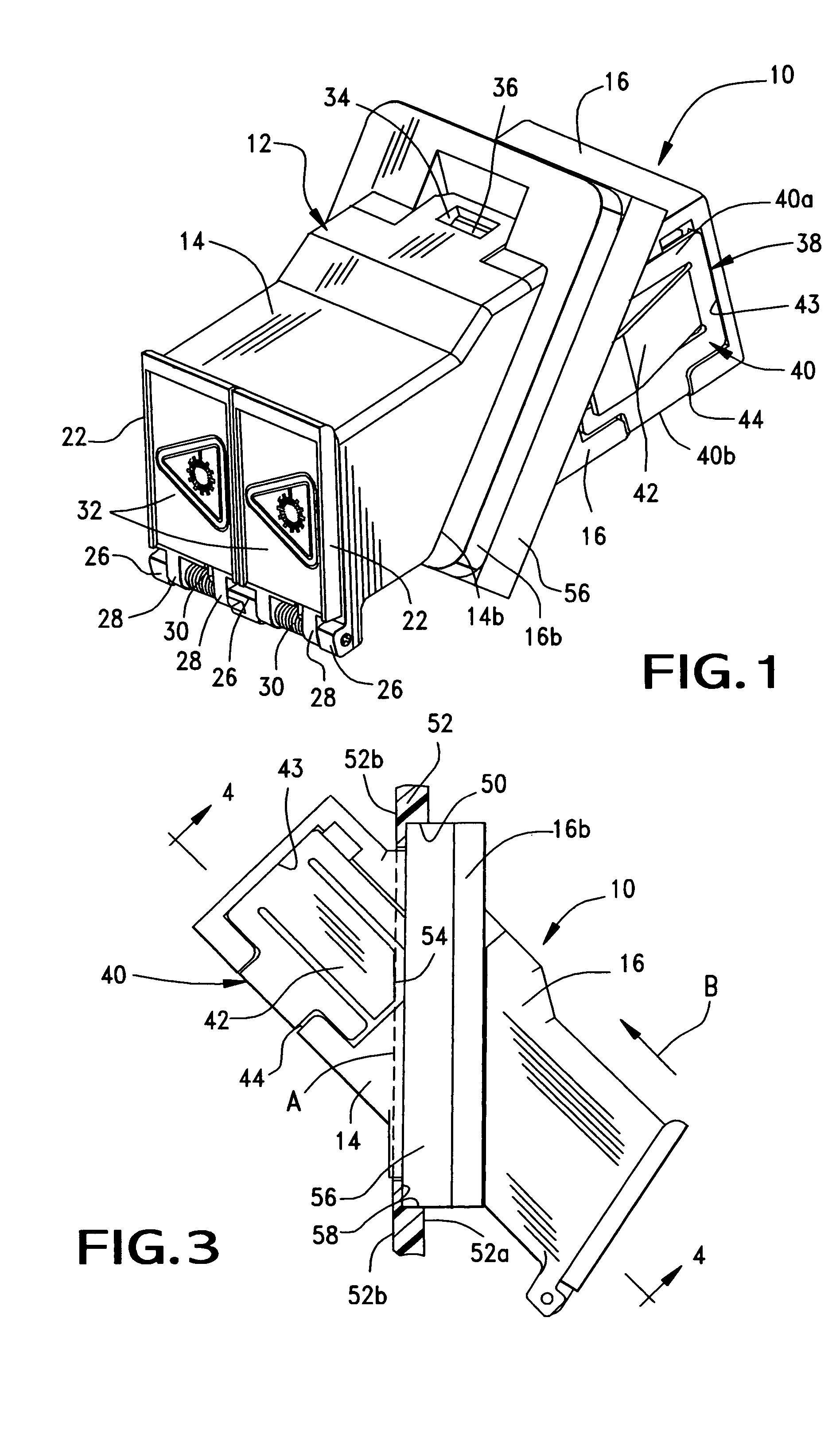
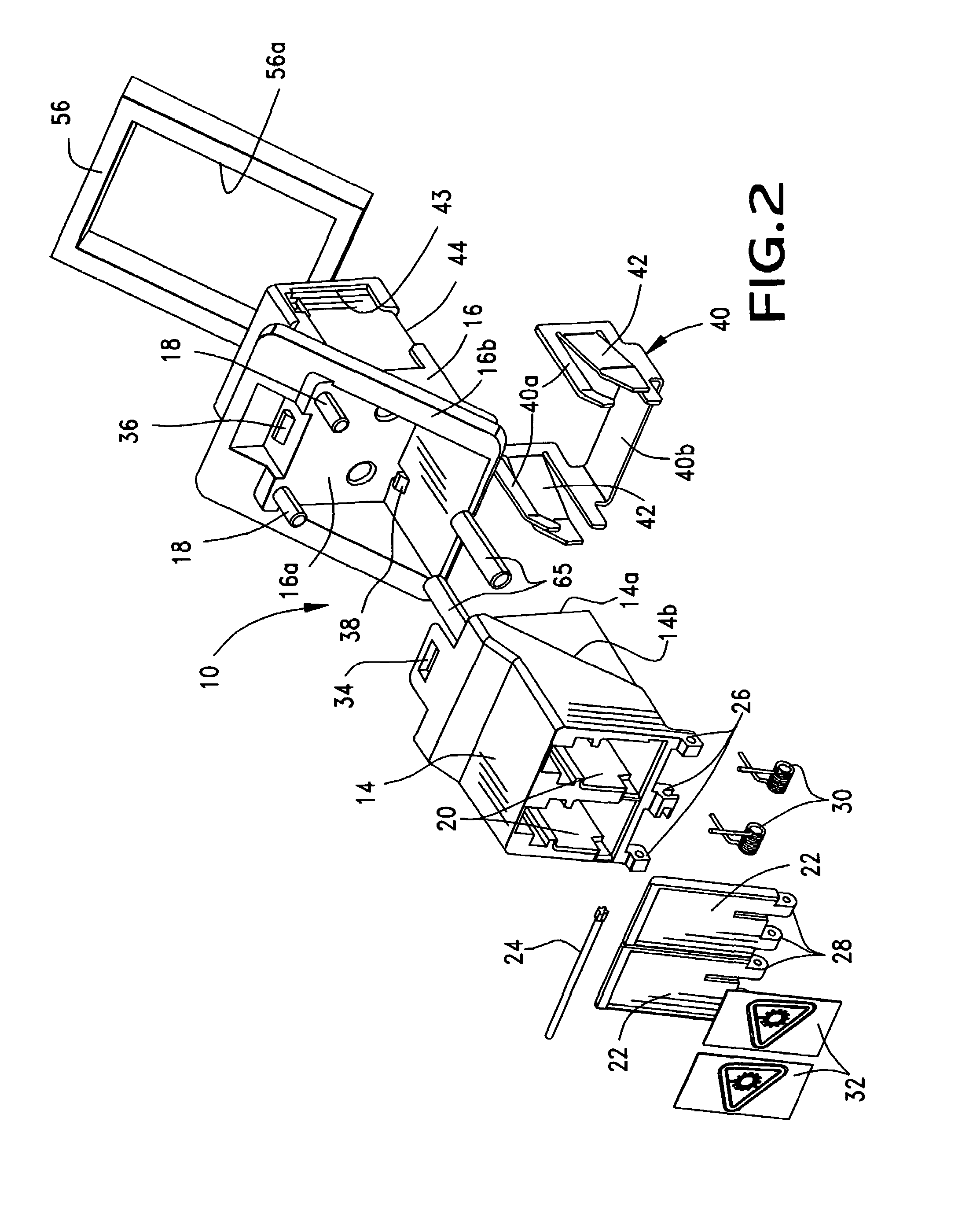
[0030]A first embodiment of the invention is shown in FIGS. 1–4 and a second embodiment of the invention is shown in FIGS. 5–15.

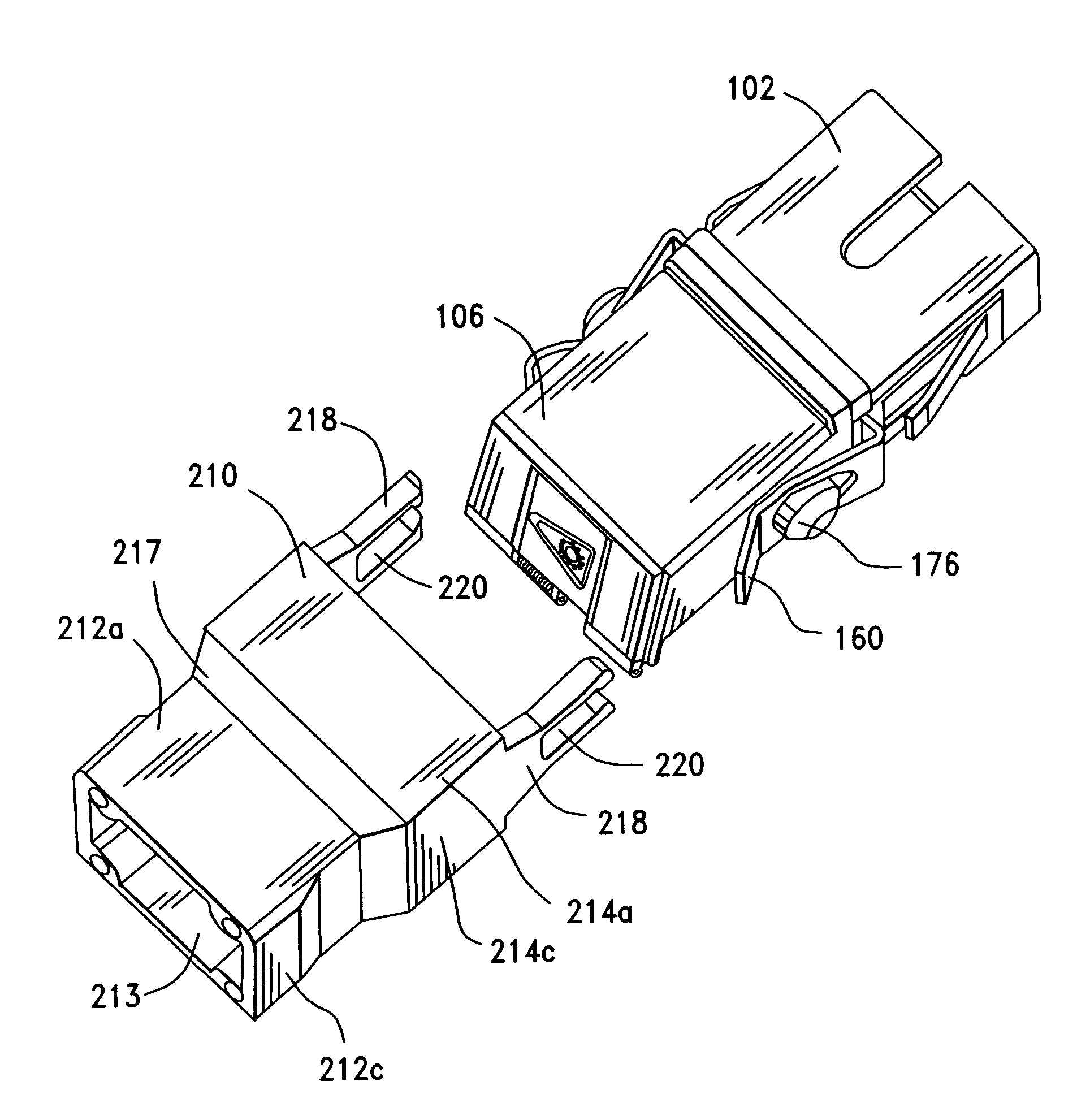
[0031]Referring to the drawings in greater detail, and first to FIGS. 1 and 2, the invention is illustrated in an adapter assembly, generally designated 10, for mounting in an opening in a panel shown in FIG. 3 and described hereinafter. The adapter assembly includes a housing, generally designated 12, which is mountable in the opening in the panel and which includes a pair of housing halves 14 and 16 which are connected together at an interface defined by an abutting interior wall 14a (FIG. 2) of housing half 14 and an interior wall 16a of housing half 16. A pair of alignment pins 18 (FIG. 2) project from interior wall 16a of housing half 16 into a pair of alignment holes (not visible in the drawings) in interior wall 14a of housing half 14.

[0032]At this point, it should be understood that, although adapter assembly 10 disclosed herein is a receptacle or a...


PUM


Abstract

An adapter assembly is provided for mounting in an opening in a panel. The assembly includes a permanent housing and a mounting bracket. The mounting bracket has latch arms for securing the permanent housing within the panel opening and mating arms for receiving an interchangeable housing to be mated with the permanent housing. A dust cap can be provided to protect the permanent housing when no interchangeable housing is mated to the permanent housing. The dust cap can also be used as a removal tool to remove an interchangeable housing from the permanent housing.

Description

RELATED APPLICATIONS[0001]This application is a continuation-in-part patent application Ser. No. 10 / 797,431 filed on Mar. 10, 2004 now abandoned which is a continuation of patent application Ser. No. 10 / 376,171 filed on Feb. 27, 2003, now issued U.S. Pat. No. 6,715,928 issued on Apr. 6, 2004.FIELD OF THE INVENTION[0002]This invention generally relates to the art of fiber optic connectors, electrical connectors and other such connecting devices and, particularly, to a system for mounting connectors in an opening in a panel, circuit box, circuit board or other substrate. The invention also relates to a mounting plate which secures a permanent housing in an opening in a panel and also engages an interchangeable housing with the permanent housing.BACKGROUND OF THE INVENTION[0003]Fiber optic connectors, electrical connectors, adapters for such connectors and variety of other such connecting devices often are mounted within openings in a panel. The connecting interface of the connector, t...

Claims


Application Information

Patent Timeline
Patent Type & Authority Patents(United States)
IPC IPC(8): H01R13/73H02B1/01G02B6/38G02B6/42
CPCG02B6/4277G02B6/3897G02B6/3849G02B2006/4297
Inventor ERNST, SCOT A.MAKHLIN, ILYA
Owner MOLEX INC
Why Eureka
Try Eureka