Mechanical thrombectomy device for use in cerebral vessels

a thrombosis device and cerebral vein technology, applied in the field of improved apparatus and methods for removing vascular occlusions, can solve the problems of clotting agents, affecting the effect of thrombosis, so as to enhance the effect of retrograde flow and increase the level of retrograde flow

Inactive Publication Date: 2006-04-18
WL GORE & ASSOC INC
View PDF15 Cites 101 Cited by
  • Summary
  • Abstract
  • Description
  • Claims
  • Application Information

AI Technical Summary

Benefits of technology

[0014]It also is an object of the present invention to provide apparatus and methods that quickly and efficiently treat cerebral occlusions while reducing trauma imposed upon cerebral vessels.
[0021]At this time, the thrombectomy device may be retracted proximally to cause the deployable element to snare the occlusion, and / or rotated circumferentially to cause the deployable element to engage and wrap fibrin strands of the occlusion about the deployable element. Emboli generated during the procedure are directed into the emboli removal catheter due to the established retrograde flow in the treatment vessel. An increased level of retrograde flow temporarily may be provided through the emboli removal catheter to enhance retrograde flow during disruption of the occlusion. Upon satisfactory removal of thrombi and / or emboli, the deployable element is retracted proximally and contracted against the distal end of the emboli removal catheter, then removed from the patient's vessel.

Problems solved by technology

Many current technologies for treating stroke are inadequate because emboli generated during the procedure may travel downstream from the original occlusion and cause ischemia.
A drawback associated with such technology is that delivering drugs may require a period of up to six hours to adequately treat the occlusion.
Another drawback associated with lytic agents (i.e., clot dissolving agents) is that they often facilitate bleeding.
However, in the event that emboli are generated during mechanical disruption of the thrombus, it is imperative that they be subsequently removed from the vasculature.
A primary drawback associated with the device described in the Wensel patent is that the deployed coil contacts the intima of the vessel, and may damage the vessel wall when the coil is retracted to snare the occlusion.
Additionally, the configuration of the coil is such that the device may not be easily retrieved once it has been deployed.
For example, once the catheter has been withdrawn and the coil deployed distal of the occlusion, it may be difficult or impossible to exchange the coil for another of different dimensions.
Like the Wensel device, the device described in the Engelson patent is depicted as contacting the intima of the vessel, and presents the same risks as the Wensel device.

Method used


Image

  • Mechanical thrombectomy device for use in cerebral vessels
  • Mechanical thrombectomy device for use in cerebral vessels
  • Mechanical thrombectomy device for use in cerebral vessels

Examples


Embodiment Construction

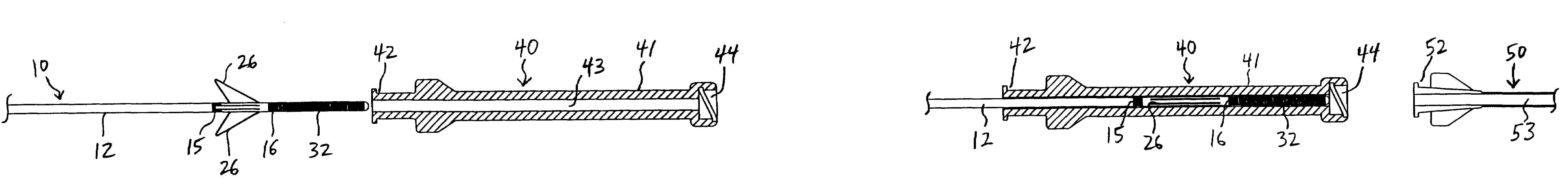
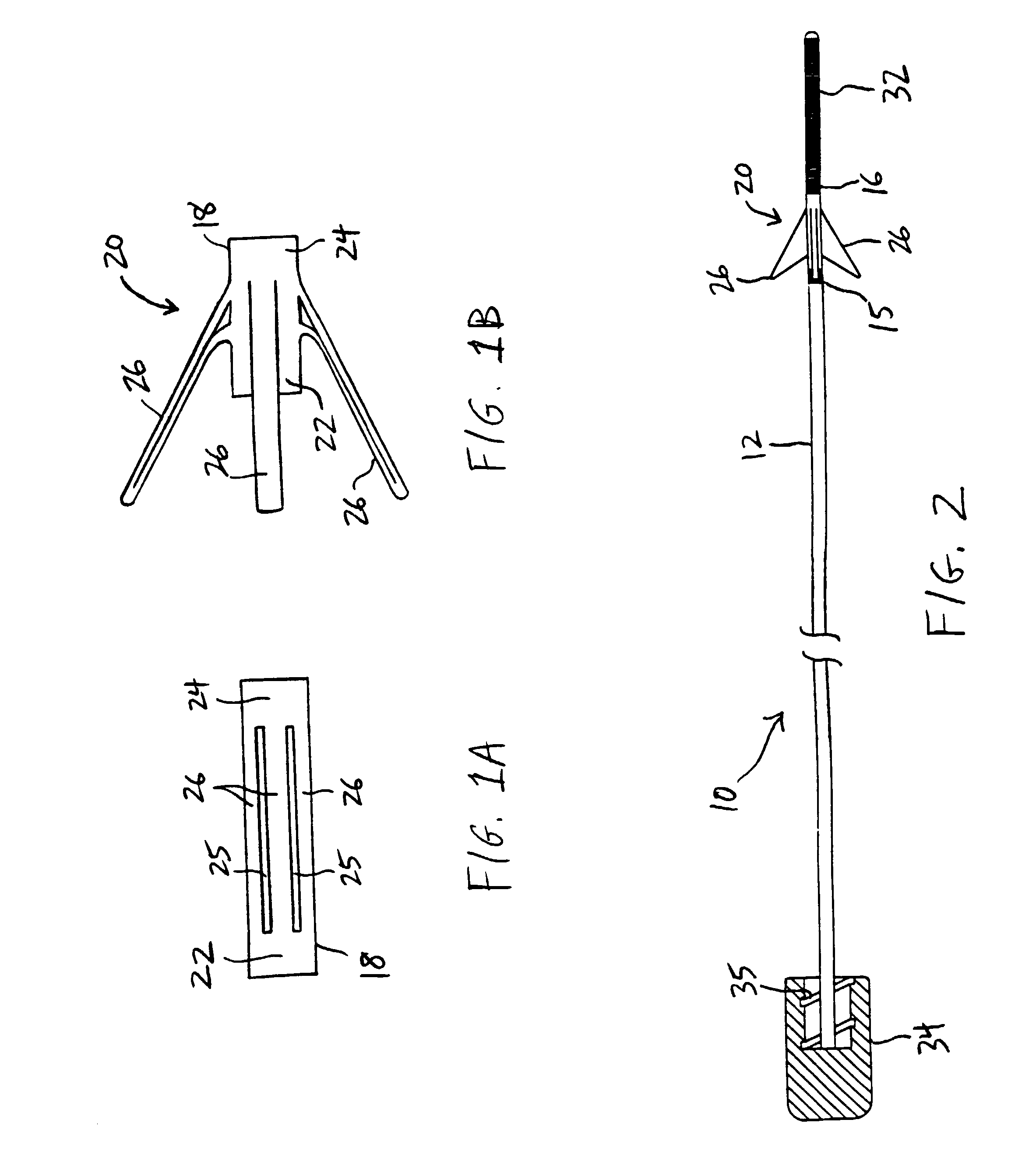
[0033]Referring to FIG. 1, a preferred method for manufacturing a hook-shaped deployable element, for use with a thrombectomy device of the present invention, is described. In FIG. 1A, tubular member 18 having proximal and distal ends 22 and 24 and a lumen extending therebetween is provided and preferably comprises a shape memory material, for example, a nickel-titanium alloy (commonly known in the art as Nitinol). Plurality of longitudinal slits 25 are formed at selected locations about the circumference of tubular member 18 to define at least one deployable element 26. As shown in FIG. 1A, plurality of longitudinal slits 25 preferably are disposed about tubular member 18 so that they do not extend to proximal and distal ends 22 and 24 of tubular member 18.

[0034]When proximal end 22 is advanced distally with respect to distal end 24, and / or distal end 24 is advanced proximally with respect to proximal end 22, deployable element 26 becomes biased radially outward from tubular member...


PUM


Abstract

Apparatus and methods for treating cerebral occlusions are provided, including a thrombectomy device having at least one deployable element. The deployable element is advanced through the occlusion in a contracted state, then self-deploys distal of the occlusion or, alternatively, may be deployed to a wide range of configurations using a physician-actuated deployment knob. The thrombectomy device then may be retracted to cause the deployable element to snare the occlusion, and / or rotated circumferentially to cause the fibrin strands of the occlusion to be wrapped around the deployable element.

Description

REFERENCE TO RELATED APPLICATION[0001]The present application is a continuation-in-part of U.S. patent application Ser. No. 09 / 972,225, filed Oct. 4, 2001.FIELD OF THE INVENTION[0002]The present invention relates to improved apparatus and methods for removal of vascular occlusions. More specifically, the apparatus and methods of the present invention are directed to removing cerebral occlusions by providing a device having at least one deployable element configured to snare and / or rotationally engage fibrin strands of the occlusion.BACKGROUND OF THE INVENTION[0003]Cerebral occlusions that lead to stroke require swift and effective therapy to reduce morbidity and mortality rates associated with the disease. Many current technologies for treating stroke are inadequate because emboli generated during the procedure may travel downstream from the original occlusion and cause ischemia. There is currently a need for a stroke treatment system that provides a swift and efficient treatment fo...

Claims


Application Information

Patent Timeline
Patent Type & Authority Patents(United States)
IPC IPC(8): A61M29/00A61B17/12A61B17/22A61B17/34A61F2/958
CPCA61B17/12136A61B17/22A61B17/22031A61B17/221A61B17/3207A61B17/12109A61B17/12022A61M2025/1052A61B2017/22034A61B2017/22044A61B2017/22094A61B2017/3435A61M25/1002A61M2025/09008A61M2025/09083A61M2025/09166A61M29/00
Inventor SCHONHOLZ, CLAUDIO JAVIERDORROS, GERALDHOGENDIJK, MICHAEL
Owner WL GORE & ASSOC INC
Why Eureka
Try Eureka