Apparatus and methods for treating stroke and controlling cerebral flow characteristics

a technology of cerebral flow and apparatus, applied in the direction of catheters, guide wires, therapy, etc., can solve the problems of clotting agents, occlusion of stroke patients, and insufficient current stroke treatment technology, so as to facilitate emboli removal and enhance flow manipulation

Inactive Publication Date: 2005-12-01
WL GORE & ASSOC INC
View PDF73 Cites 81 Cited by
  • Summary
  • Abstract
  • Description
  • Claims
  • Application Information

AI Technical Summary

Benefits of technology

[0025] It is a further object of the present invention to provide apparatus and methods that quickly and efficiently treat cerebral occlusions.
[0026] It still a further object of the present invention to provide apparatus and methods for selectively providing retrograde and / or antegrade flow to desired regions in the cerebral vasculature to effectively remove emboli.
[0029] One or more flow control devices, each having a rapidly deployable occlusive member, then are positioned at selected locations, e.g., in the subclavian arteries, and may be deployed to isolate or redistribute flow through the cerebral vasculature. Preferably, the flow control devices occlude blood flow in the vertebral and carotid arteries in the hemisphere in which the occlusion is not located. This temporarily influences flow in the opposing hemisphere. Preferably, the flow control devices are provided in sufficient number that, when deployed, the flow control devices substantially influence the flow dynamic of mid-cerebral artery.
[0034] The second emboli removal catheter may be used to enhance flow manipulation in the Circle of Willis and communicating vessels to facilitate removal of emboli via either retrograde or antegrade flow either independently or, or simultaneously with, use of the first emboli removal catheter.

Problems solved by technology

Many current technologies for treating stroke are inadequate because emboli generated during the procedure may travel downstream from the original occlusion and cause ischemia.
A drawback associated with such technology is that delivering drugs may require a period of up to six hours to adequately treat the occlusion.
Another drawback associated with lytic agents (i.e., clot dissolving agents) is that they often facilitate bleeding.
However, in the event that emboli are generated during mechanical disruption of the thrombus, it is imperative that they be subsequently removed from the vasculature.
Such treatment methods do not attempt to manipulate flow characteristics in the cerebral vasculature, e.g, the Circle of Willis and communicating vessels, such that emboli may be removed.
For example, if the first balloon of the first tubular member is deployed in the left common carotid artery, as shown in FIG. 7C, aspiration of blood from the vessel between the balloon and the occlusion may cause the vessel to collapse.
On the other hand, if the balloon is not deployed, failure to stabilize the distal tip may result in damage to the vessel walls.
In addition, failure to occlude the vessel may permit antegrade blood flow to diverted into that apparatus, rather than blood distal to the first tubular member.
However, when that balloon is deployed, the contralateral artery may be starved of sufficient flow, since the only other flow in that artery is that aspirated through the first tubular member.
On the other hand, if the balloon of the second tubular member is not inflated, no flow control is possible.
First, the use of a vacuum to aspirate the occlusion requires an external pressure monitoring device.
The application of too much vacuum pressure through the aspiration port may cause trauma, i.e., collapse, to the vessel wall.
The use of a chopping mechanism, however, may generate such a large quantity of emboli that it may be difficult to retrieve all of the emboli.
In addition, emboli generated by the action of the chopping mechanism may accumulate alongside the catheter, between the aspiration port and the distal balloon.
Yet another drawback of the device described in the Barbut '199 patent is that high-pressure perfusion in collateral arteries may not augment retrograde flow distal to the occlusion as hypothesized.
Antegrade blood flow from the heart in unaffected arteries, e.g., other vertebral and / or carotid arteries, may make it difficult for the pressure differential induced in the contralateral arteries to be communicated back to the occluded artery in a retrograde fashion.
One drawback associated with the technique described in the Frazee patent is that the pressure in the transverse venous sinuses must be continuously monitored to ensure that cerebral edema is avoided.
Because the veins are much less resilient than arteries, the application of sustained pressure on the venous side may cause brain swelling, while too little pressure may result in insufficient blood delivered to the arterial side.
A primary drawback associated with the Wensel device is that the deployed coil contacts the intima of the vessel, and may damage to the vessel wall when the coil is retracted to snare the occlusion.
Additionally, the configuration of the coil is such that the device may not be easily retrieved once it has been deployed.
For example, once the catheter has been withdrawn and the coil deployed distal to the occlusion, it will be difficult or impossible to exchange the coil for another of different dimensions.
Like the Wensel device, the Engelson device is depicted as contacting the intima of the vessel, and presents the same risks as the Wensel device.

Method used


Image

  • Apparatus and methods for treating stroke and controlling cerebral flow characteristics
  • Apparatus and methods for treating stroke and controlling cerebral flow characteristics
  • Apparatus and methods for treating stroke and controlling cerebral flow characteristics

Examples


Embodiment Construction

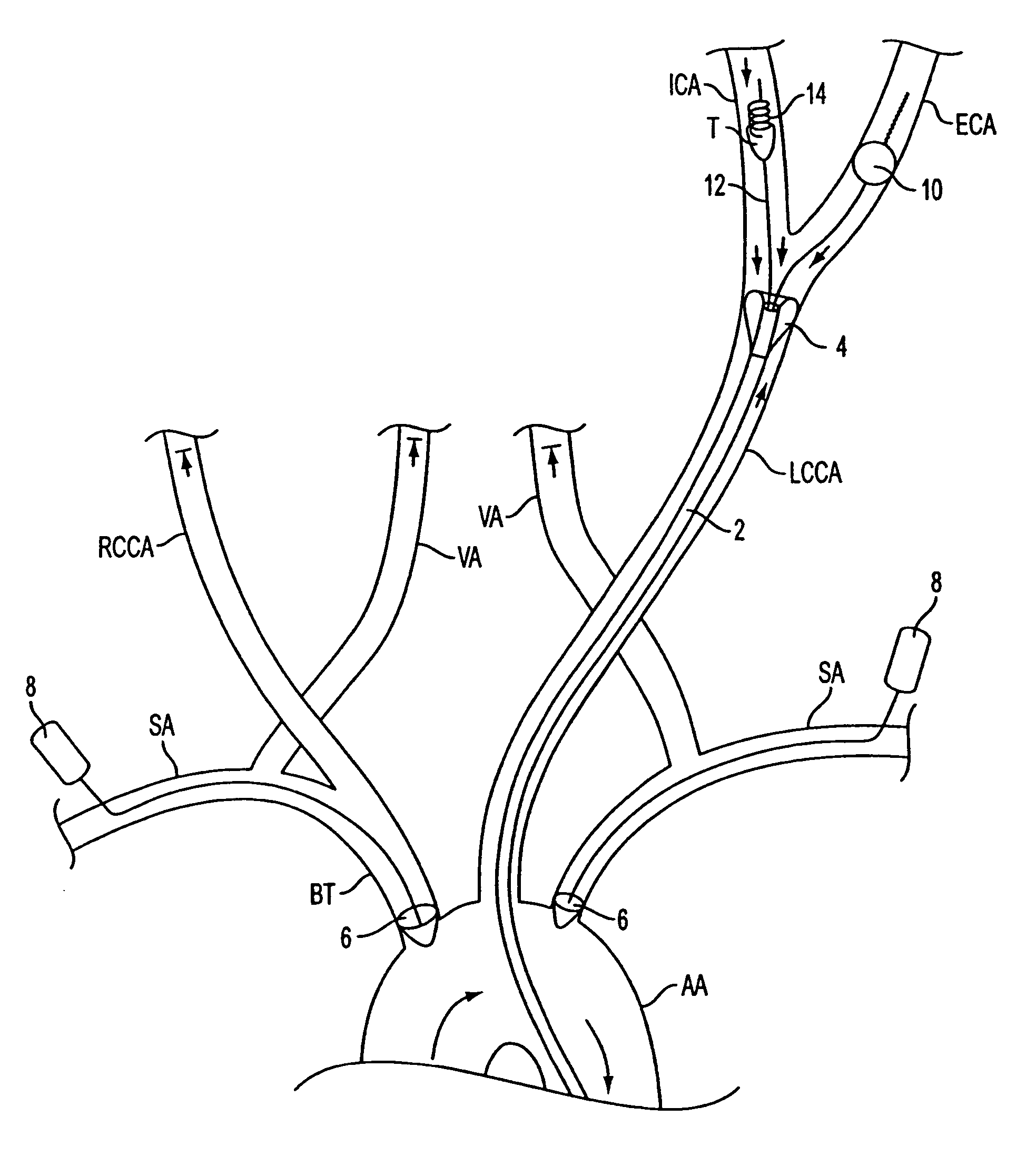
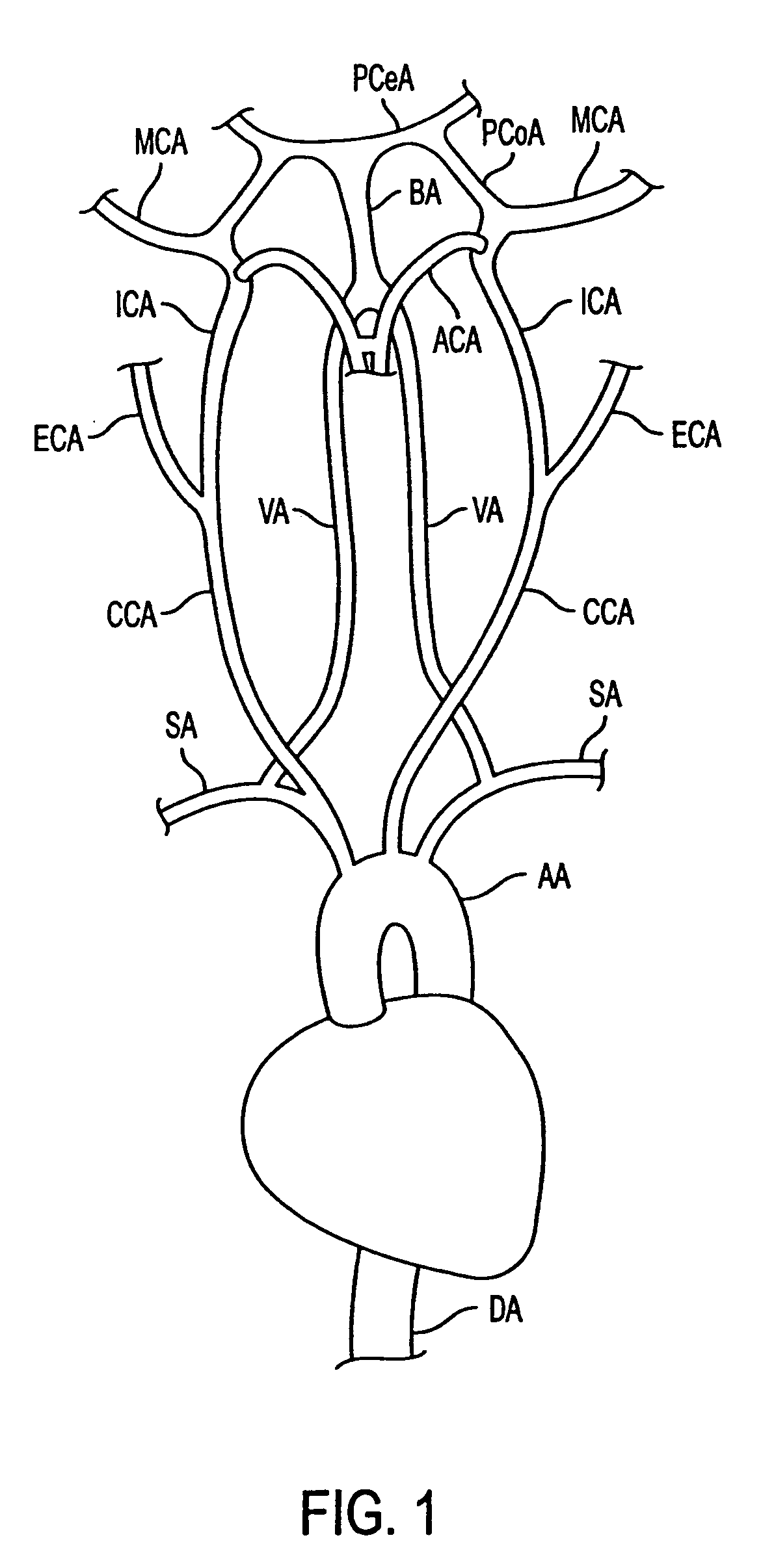
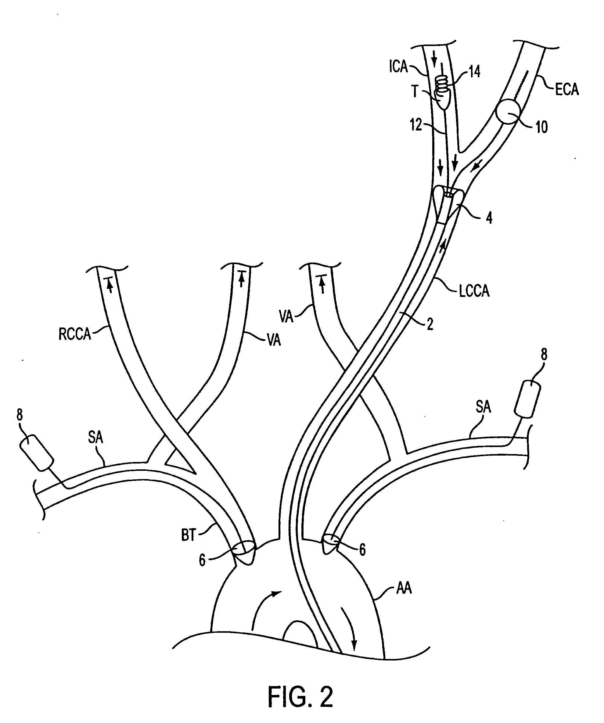
[0051] Referring to FIG. 1, a schematic of the pertinent vasculature relating to the present invention is provided. Many cerebral obstructions that lead to stroke reside in the middle cerebral arteries MCA. To treat obstructions in the MCA, one approach involves percutaneously and transluminally advancing a therapeutic device to the site of the obstruction via the internal carotid artery ICA.

[0052] It is well known in the art to percutaneously and transluminally advance a catheter in retrograde fashion toward coronary vasculature, e.g., via the femoral artery, external iliac artery, descending aorta DA and aortic arch AA. To access cerebral vasculature, including obstructions residing in the MCA, one approach is to further advance a catheter and / or therapeutic devices in antegrade fashion from the aortic arch AA, into the common carotid artery CCA, up through the ICA and into the middle cerebral artery MCA, as shown in FIG. 1.

[0053] Treating occlusions in the MCA may generate embo...


PUM


Abstract

Apparatus and methods for treatment of stroke are provided. In a preferred embodiment, the present invention disposes at least one catheter having a distal occlusive member in either the common carotid artery (CCA) or both the vertebral artery (VA) and the CCA on the hemisphere of the cerebral occlusion. Blood flow in the opposing carotid and / or vertebral arteries may be inhibited. Retrograde or antegrade flow may be provided through either catheter independently to effectively control cerebral flow characteristics. Under such controlled flow conditions, a thrombectomy device may be used to treat the occlusion, and any emboli generated are directed into the catheter(s).

Description

RELATED APPLICATIONS [0001] The present application is a divisional of copending U.S. patent application Ser. No. 09 / 972,231 filed Oct. 4, 2001.FIELD OF THE INVENTION [0002] The present invention relates to improved apparatus and methods for treatment of stroke. More specifically, the apparatus and methods of the present invention are directed to treating stroke by controlling cerebral blood flow and removing thrombi and / or emboli. BACKGROUND OF THE INVENTION [0003] Cerebral occlusions that lead to stroke require swift and effective therapy to reduce morbidity and mortality rates associated with the disease. Many current technologies for treating stroke are inadequate because emboli generated during the procedure may travel downstream from the original occlusion and cause ischemia. There is currently a need for a stroke treatment system that provides a swift and efficient treatment for occlusions while simultaneously controlling cerebral flow characteristics. [0004] In the initial s...

Claims


Application Information

Patent Timeline
Patent Type & Authority Applications(United States)
IPC IPC(8): A61B17/12A61B17/22A61B17/34A61F2/958
CPCA61B17/12022A61M2025/1052A61B17/12109A61B17/12136A61B17/12172A61B17/22A61B17/221A61B17/3207A61B2017/22034A61B2017/3435A61M25/1002A61M2025/09008A61M2025/09083A61M2025/09166A61B17/12045
Inventor DORROS, GERALDPARODI, JUAN CARLOSSCHONHOLZ, CLAUDIO JAVIERHOGENDIJK, MICHAEL
Owner WL GORE & ASSOC INC
Why Eureka
Try Eureka