Audio signal processing apparatus
a technology of audio signal and processing apparatus, which is applied in the direction of recording signal processing, instrument details, and semiconductor/solid-state device details, etc., can solve the problem of significant redundancy of sampled or uniformly quantized audio signals
- Summary
- Abstract
- Description
- Claims
- Application Information
AI Technical Summary
Benefits of technology
Problems solved by technology
Method used
Image
Examples
first embodiment
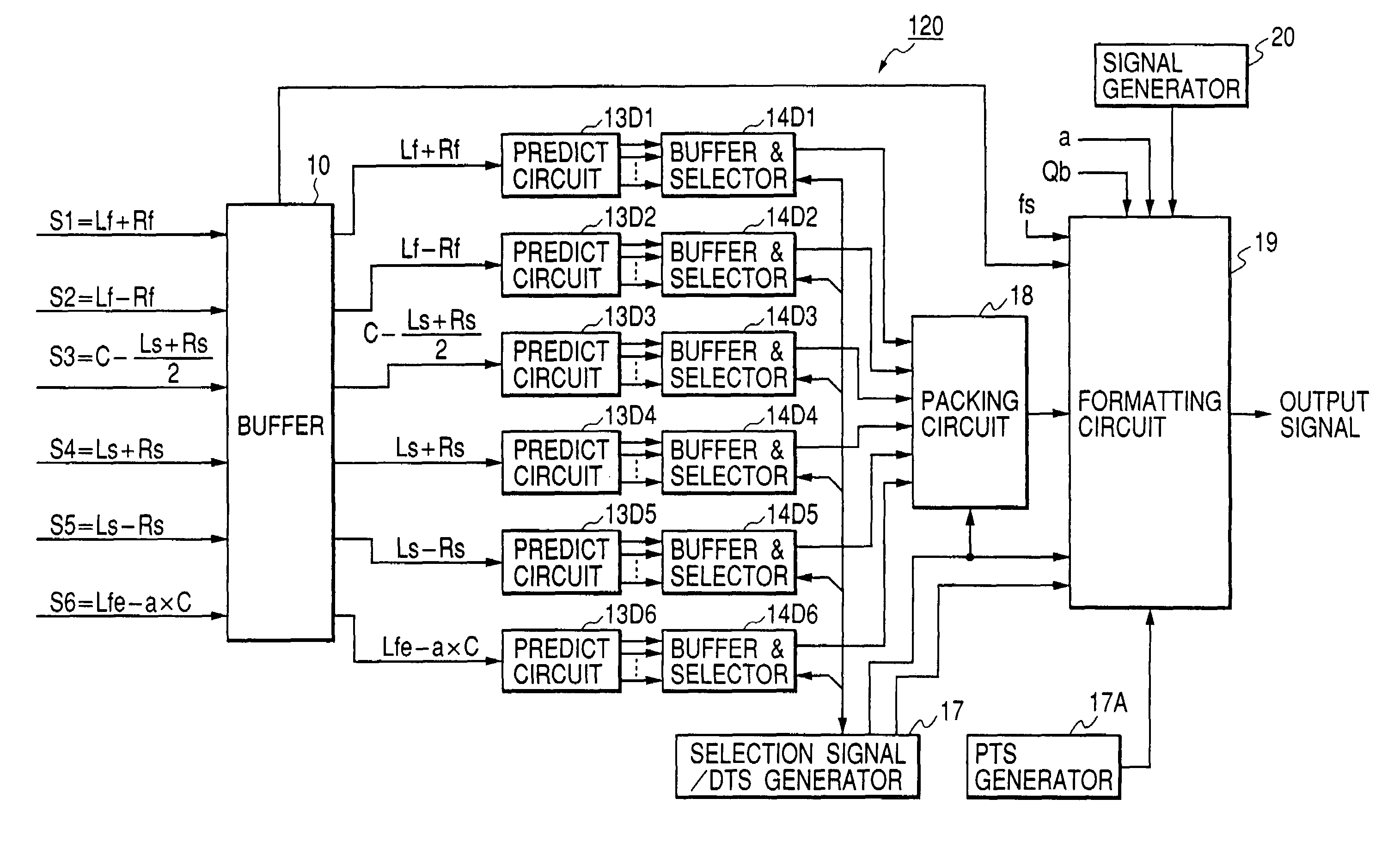
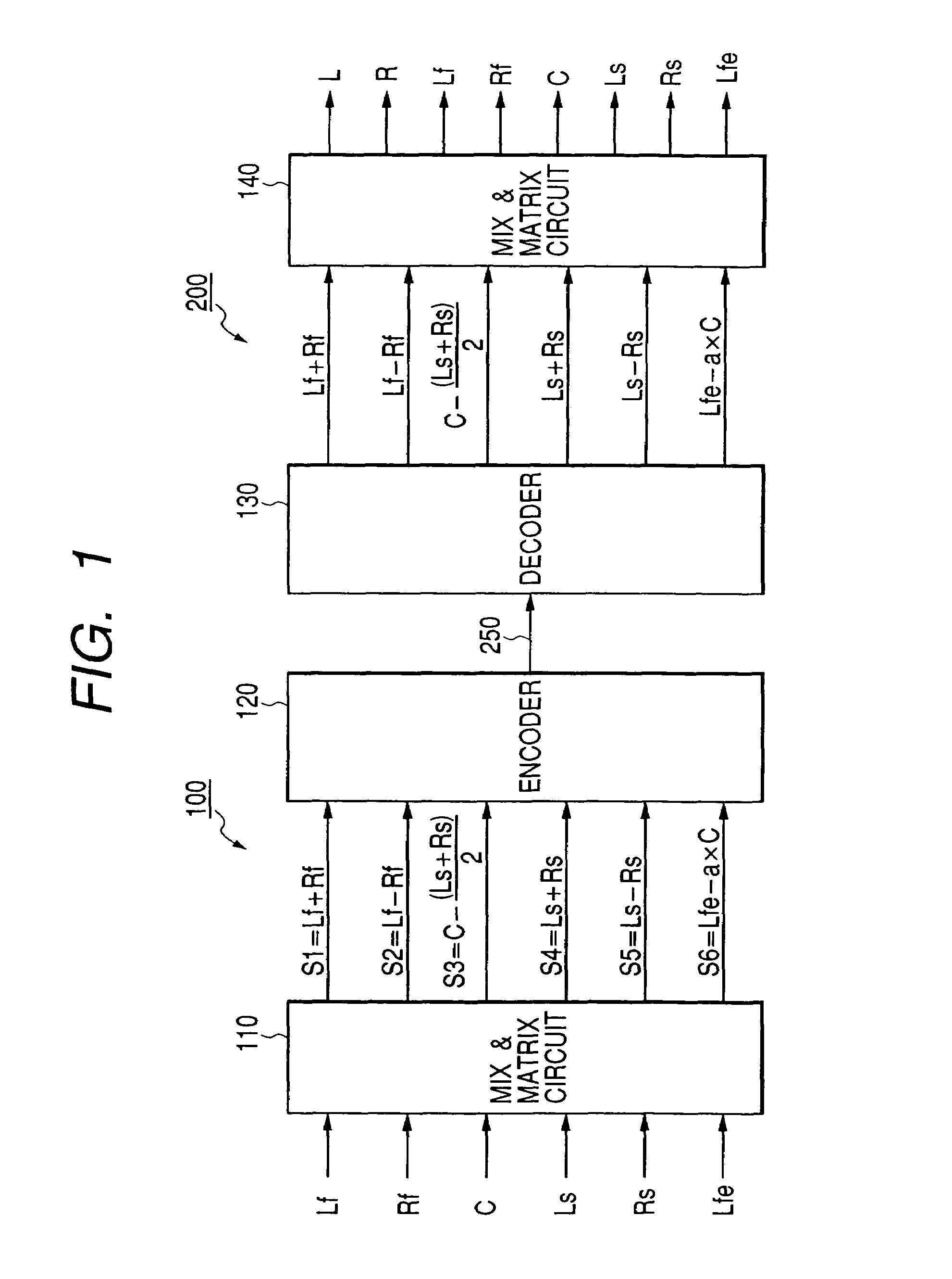
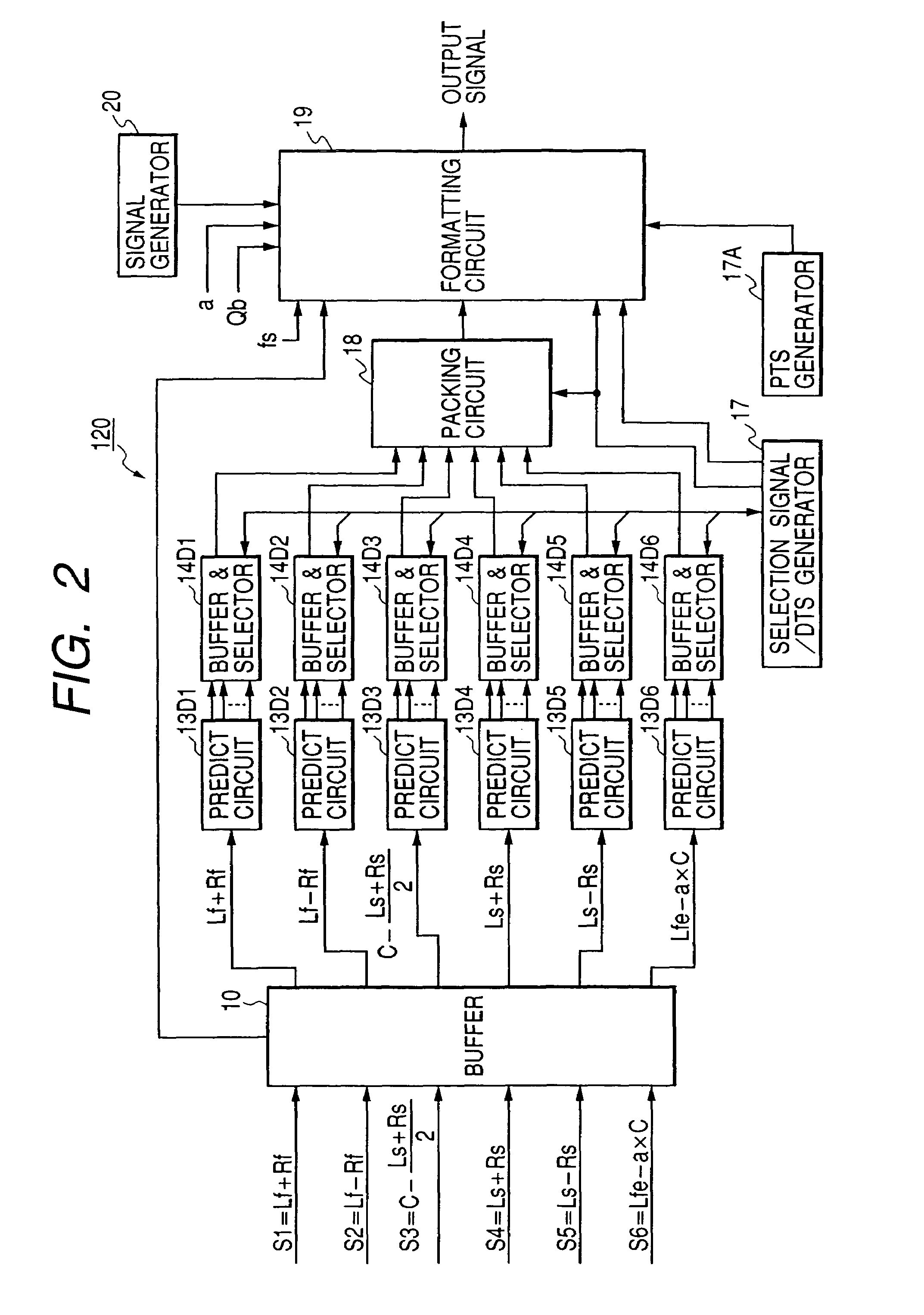
[0055]With reference to FIG. 1, an audio signal encoding apparatus 100 includes a mix and matrix circuit 110 and an encoder 120.
[0056]The mix and matrix circuit 110 is followed by the encoder 120. An audio signal decoding apparatus 200 includes a decoder 130 and a mix and matrix circuit 140. The decoder 130 is followed by the mix and matrix circuit 140. The audio signal encoding apparatus 100 and the audio signal decoding apparatus 200 are connected via a transmission line 250. The transmission line 250 includes a communication line or a communication network. Alternatively, the transmission line 250 may include a combination of a recording unit, a recording medium, and a reproducing unit. For example, the recording medium is a DVD-audio, another optical disc, or a magnetic disc.
[0057]The audio signal encoding apparatus 100 receives 6-channel input digital audio signals, that is, a left-front digital audio signal Lf, a right-front digital audio signal Rf, a center digital audio sign...
second embodiment
[0126]A second embodiment of this invention is similar to the first embodiment thereof except for design changes mentioned later.
[0127]With reference to FIG. 11, the second embodiment of this invention includes a packeting processor 350 which follows the audio signal encoding apparatus 100. The packeting processor 350 encodes the output signal of the audio signal encoding apparatus (that is, the main bit stream) into a packet stream. The packeting processor 350 transmits the packet stream to a communication network (or a communication line) 360.
[0128]A de-packeting processor 370 receives the packet stream from the communication network 360. The de-packeting processor 370 decodes the packet stream into the main bit stream. The de-packeting processor 370 outputs the main bit stream to the audio signal decoding apparatus 200. The packeting processor 350 operates in accordance with a control program stored in its internal ROM or another memory. FIG. 12 is a flowchart of a segment of the...
third embodiment
[0130]A third embodiment of this invention is similar to the first embodiment thereof except for design changes indicated hereinafter. In the third embodiment of this invention, an audio signal encoding apparatus includes a down mixing circuit which converts a set of 6-channel input digital audio signals Lf, Rf, C, Ls, Rs, and Lfe into a pair of a left-channel digital audio signal L and a right-channel digital audio signal R as the mix and matrix circuit 140 in the first embodiment of this invention does. A mix and matrix circuit following the down mixing circuit converts a set of the digital audio signals L, R, C, Ls, Rs, and Lfe into a set of a calculation-result signal L+R, a calculation-result signal L−R, a calculation-result signal C−(Ls+Rs) / 2, a calculation-result signal Ls+Rs, a calculation-result signal Ls−Rs, and a calculation-result signal Lfe−C. The calculation-result signals L+R, L−R, C−(Ls+Rs) / 2, Ls+Rs, Ls−Rs, and Lfe−C are encoded as the calculation-result signals Lf+R...
PUM
 Abstract
Description
Claims
Application Information
 - R&D
- Intellectual Property
- Life Sciences
- Materials
- Tech Scout
- Unparalleled Data Quality
- Higher Quality Content
- 60% Fewer Hallucinations
Browse by: Latest US Patents, China's latest patents, Technical Efficacy Thesaurus, Application Domain, Technology Topic, Popular Technical Reports.
© 2025 PatSnap. All rights reserved.Legal|Privacy policy|Modern Slavery Act Transparency Statement|Sitemap|About US| Contact US: help@patsnap.com


