Respiratory flow sensor

a technology of respiratory system and sensor, applied in the field of respiratory system sensor, can solve the problems of unreliability of standard differential pressure flow sensor, affecting the accuracy of pressure measurement,

Inactive Publication Date: 2006-04-25
GENERAL ELECTRIC CO
View PDF9 Cites 25 Cited by
  • Summary
  • Abstract
  • Description
  • Claims
  • Application Information

AI Technical Summary

Benefits of technology

[0015]The invention is a differential-pressure gas flow sensor, for use in mechanical ventilators, wherein the shape of the aerodynamic strut, or interfering body, prevents the lumens at which the differential pressures are sensed from becoming obstructed by condensed water. Three unique characteristics of the shape of the interfering body, which prevent water blockage of the pressure-sensing lumen from occurring and which are points of novelty of the current invention, are:
[0018]3) Each edge portion of the interfering body slopes at an angle from the base of the interfering body to the location of the pressure-sensing lumen. Consequently, the leading edge of the interfering body (namely, the leading edge which faces towards the source of airflow) deflects the airflow along a flow vector oriented towards the pressure-sensing lumen on the opposite (trailing) edge portion in such a way as to flush condensed water out of the area of the pressure-sensing lumen.

Problems solved by technology

It is known, however, that standard differential-pressure flow sensors, as described above, suffer from several deficiencies.
In particular, standard differential pressure flow sensors have been found to function unreliably in the presence of high humidity within the respiratory gasses flowing through the sensor.
When such condensation occurs in the circular lumen in the inner wall of the flow sensor, at which site pressure measurements are sensed, water blocks the lumen, thus distorting the pressure measurements recorded by the differential-pressure flow sensor, and invalidating the resultant flow data.
This technique requires the addition of electrical wiring and machinery to the flow sensor and ventilator, thus increasing the cost and mechanical complexity of the sensor.
This alternative has proven to be impractical, as movement of the patient or the flexible respiratory tubing inevitably results in movement of the flow sensor, and thus movement of the accumulated water within the sensor, causing blockage of the pressure-sensing lumen.

Method used


Image

  • Respiratory flow sensor
  • Respiratory flow sensor
  • Respiratory flow sensor

Examples


Embodiment Construction

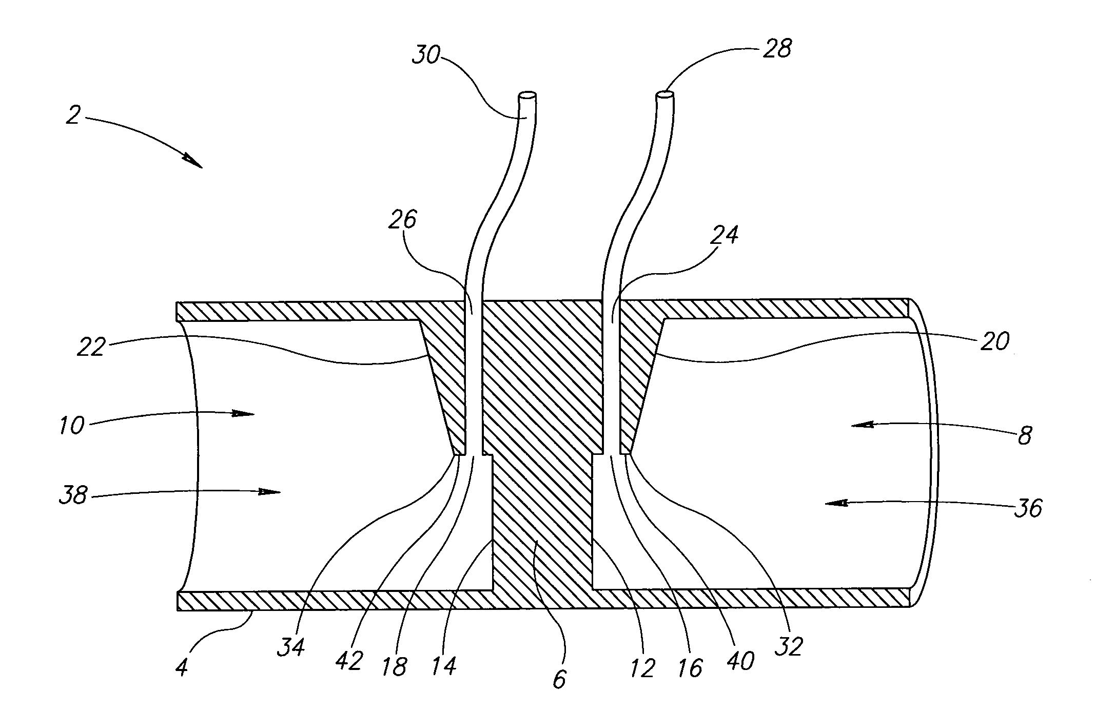
[0051]The present invention is a differential-pressure respiratory flow sensor for use in a mechanical ventilator.

[0052]The principles and operation of a differential-pressure respiratory flow sensor, according to the present invention, may be better understood with reference to the drawings and the accompanying description.

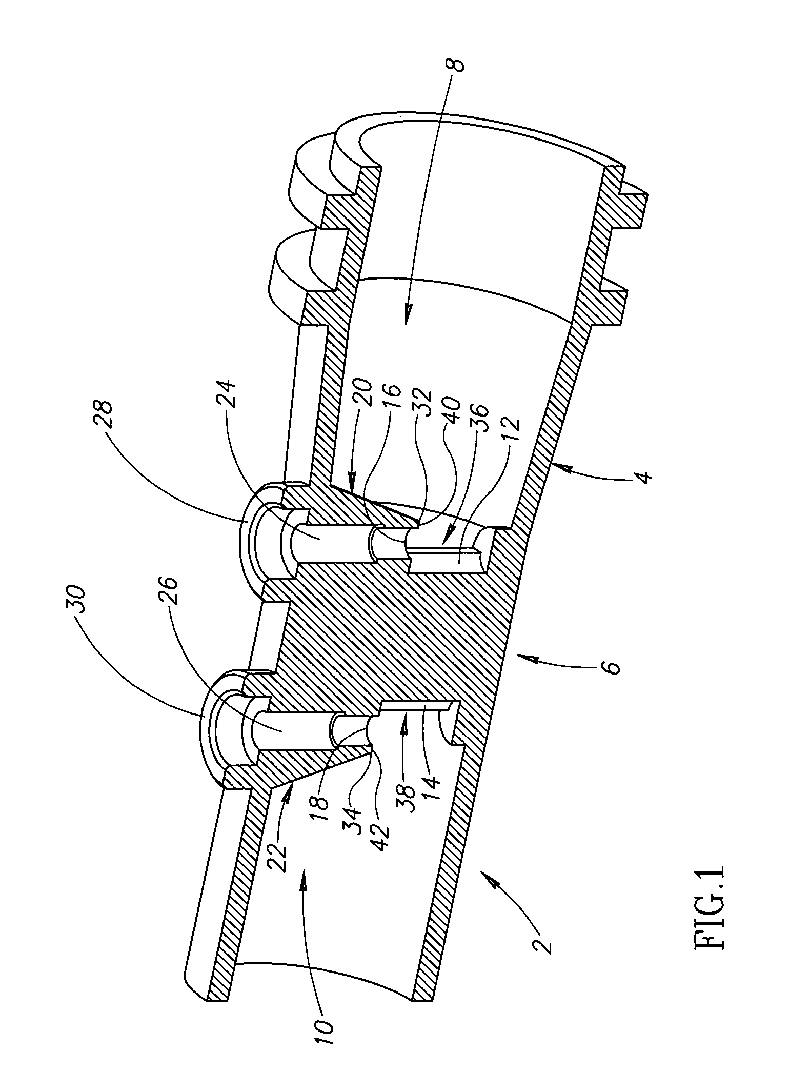
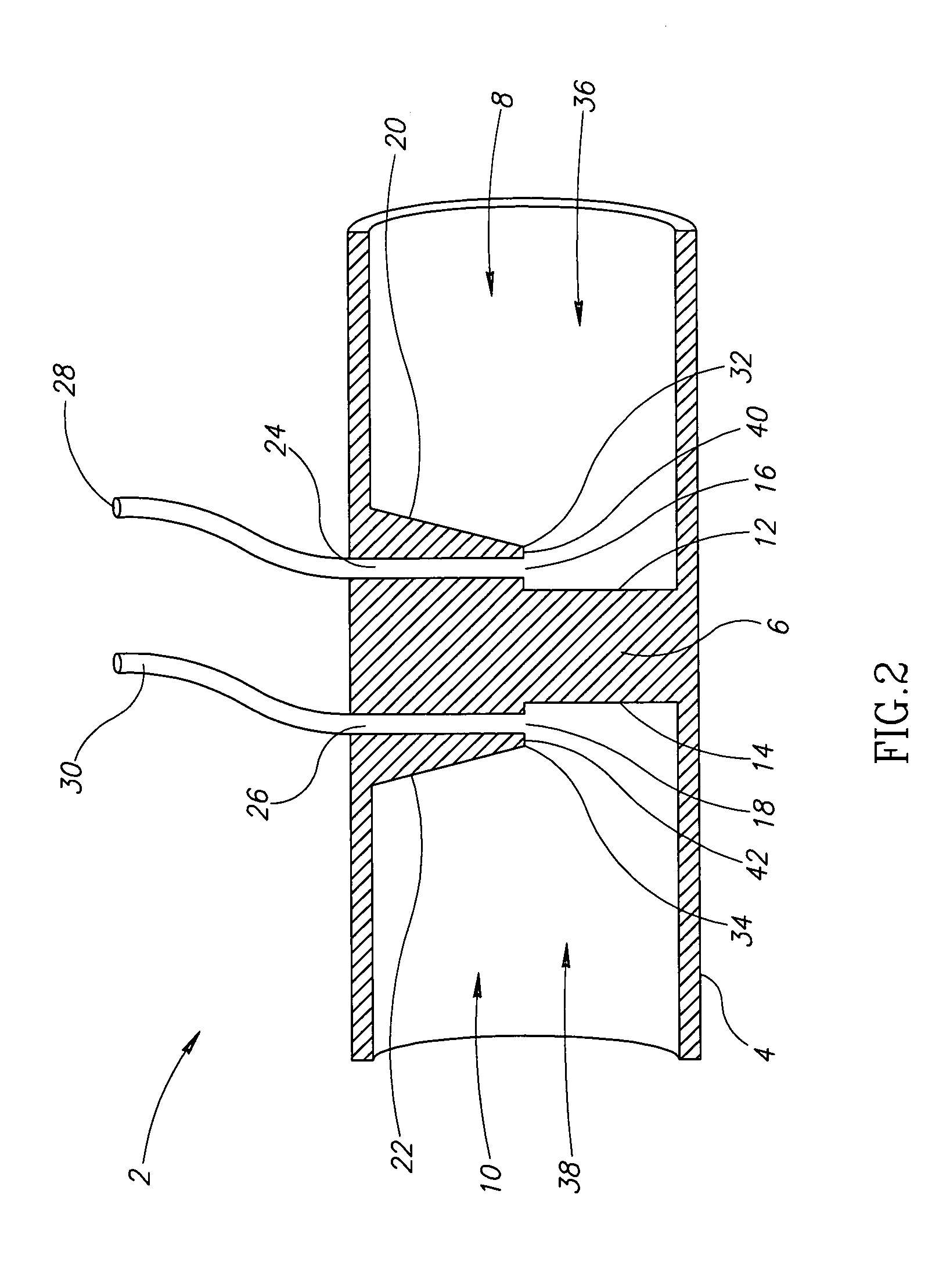
[0053]FIG. 1 shows the overall structure of the current invention. The figure can best be understood by simultaneously referring to FIGS. 2, 3, and 4, which show side, top and short-axis views respectively of the device depicted in FIG. 1. A flow sensor 2 comprises a hollow cylindrical body 4 having a bore, and an interfering body 6 disposed within the bore of cylindrical body 4. In the preferred embodiment, cylindrical body 4 is a segment of respiratory tubing, although it will be understood that any form of tubing may be used without departing from the spirit of the current invention. In terms of the current invention, the word “tube” is hereby defined as refer...


PUM


Abstract

A respiratory tract differential-pressure flow sensor, including a tube having a distal end that is insertable into a respiratory tract, an interfering body disposed within the tube proximal to the distal end and having a first edge facing one end of the tube and a second edge facing away from the end, the interfering body extending across the diameter of the tube, a first pressure sensing port operative to sense an air pressure, the first port being disposed in the first edge not abutting the wall of the tube, and a second pressure sensing port operative to sense an air pressure, the second port being disposed in the second edge not abutting the wall of the tube, where either of the edges is inclined inwardly towards the axis of the interfering body extending across the diameter of the tube.

Description

CROSS-REFERENCE TO RELATED APPLICATIONS[0001]The present application is a continuation of U.S. patent application Ser. No. 10 / 200,764, filed Jul. 24, 2002, now U.S. Pat. No. 6,802,225 entitled “Respiratory Flow Sensor,” and incorporated herein by reference in its entirety.FIELD AND BACKGROUND OF THE INVENTION[0002]The present invention relates generally to the field of medical devices and specifically to medical devices that are designed to monitor the respiratory characteristics of patient breathing, especially for those patients who are attached to mechanical ventilators.[0003]Persons exhibiting acute or chronic respiratory failure, for example due to pulmonary infection or trauma, often require artificial ventilatory support and may therefore be connected, by means of flexible plastic ventilation tubing, to a mechanical ventilator. Correct functioning of such a ventilator entails continuous, accurate and reliable monitoring, by the ventilator, of airflow characteristics within th...

Claims


Application Information

Patent Timeline
Patent Type & Authority Patents(United States)
IPC IPC(8): G01F1/37A61B5/087G01F1/40
CPCA61B5/087G01F1/46G01F1/40G01F1/37
Inventor MISHOLI, BOAZSHAHAR, MARKHAJ-YAHYA, SAJED
Owner GENERAL ELECTRIC CO
Why Eureka
Try Eureka