Emergency lighting equipment with automatic charge/discharge and monitoring system

a lighting equipment and automatic technology, applied in emergency power supply arrangements, safety/protection circuits, transportation and packaging, etc., can solve the problems of system failure, ineffective working life, and aesthetic appeal still need to be addressed

Inactive Publication Date: 2006-04-25
CASHIDO
View PDF3 Cites 27 Cited by
  • Summary
  • Abstract
  • Description
  • Claims
  • Application Information

AI Technical Summary

Benefits of technology

[0010]A second object of this invention is to provide a charge / discharge method for automatically charging or discharging the battery within an emergency lighting equipment. The automatic charge / discharge method takes care of the battery charging operation automatically in such a way that a charging operation stops after the battery is in a float-charging state for some time and a discharging operation stops after the battery is in a discharging state for some time. Therefore, the battery is prevented from having any permanent damage due to float-charging too long or over-discharging for too long.
[0015]According to one preferred embodiment of this invention, the main control unit furthermore comprises an analogue / digital circuit, a micro-controller, a charge control circuit and a discharge control circuit. The analogue / digital circuit is coupled to the battery. The analogue / digital circuit measures the amount of electrical energy stored up inside the battery and issues a measure signal. The micro-controller is coupled to the analogue / digital circuit. The micro-controller receives the measure signal and outputs a charge signal or a discharge signal according to the measure signal. The micro-controller also has a timer for counting the passage of time. When the timer in the micro-controller has detected the passage of a preset period of time within which the ac voltage source provides an ac voltage continuously without any battery discharge, a discharge signal is issued. The charge control circuit is coupled to the micro-controller and the battery. The charge control circuit receives the charge signal to initiate a battery charging operation. The discharge control circuit is coupled to the illuminating apparatus, the micro-controller and the battery. The discharge control circuit receives the discharge signal to initiate a battery discharging operation. When the battery is over-discharged, the discharge control circuit will issue a shutdown signal to turn off the illuminating apparatus. The discharge control circuit also has the capacity to control the size of current from the discharging battery so that electric power provided by the battery may last longer.

Problems solved by technology

Although most emergency lighting systems currently in the market have had many improvements, some problems including effective working life, damage warning and aesthetic appeal still need to be addressed.
Moreover, system failure is often found after an actual power outage has occurred.
Because the emergency lighting system is used mainly to prevent accidents, their failure is a serious concern.
The failure of most automatic lighting system lies typically in an inappropriate design of the battery charging / discharging unit.
In general, once an emergency lighting system is installed, nobody would take care to inspect and maintain the system periodically.
Since prolonged charging is likely to shorten the working life of a battery, the emergency lighting system has a short useful life.
Ultimately, the battery is permanently damaged.
Furthermore, failure is only found after an actual power outage has occurred.
Since there is no low voltage inspection circuit inside the system, the battery may be permanently damaged by over-discharge.
There is little control over the discharge current in an emergency lighting system.
Thus, the system will stop providing any illumination after a while if the power outage is long.

Method used


Image

  • Emergency lighting equipment with automatic charge/discharge and monitoring system
  • Emergency lighting equipment with automatic charge/discharge and monitoring system
  • Emergency lighting equipment with automatic charge/discharge and monitoring system

Examples


Embodiment Construction

[0029]Reference will now be made in detail to the present preferred embodiments of the invention, examples of which are illustrated in the accompanying drawings. Wherever possible, the same reference numbers are used in the drawings and the description to refer to the same or like parts.

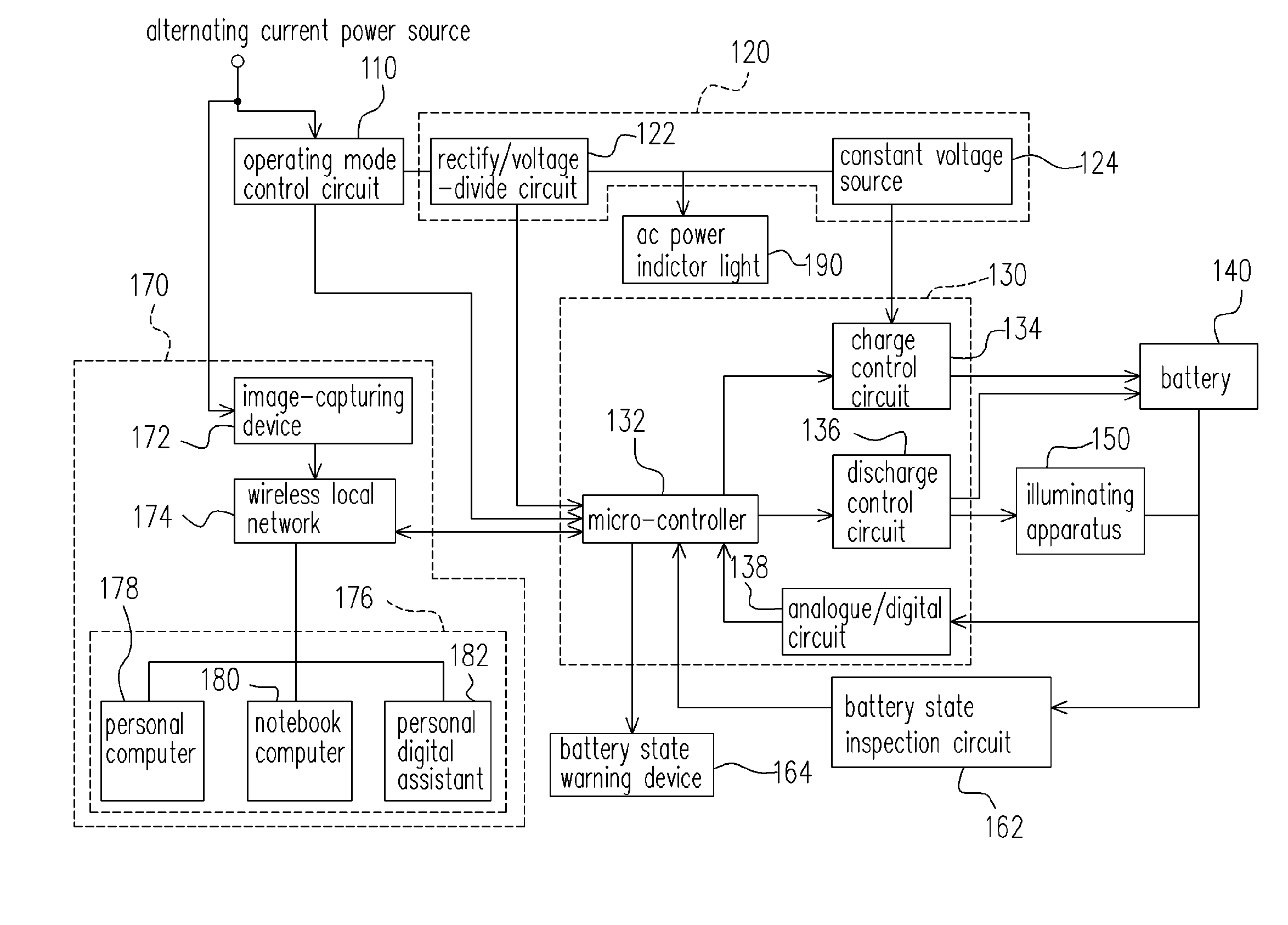
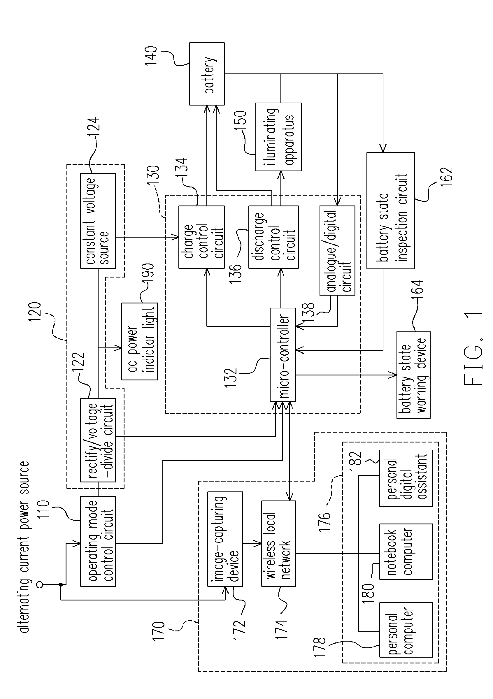
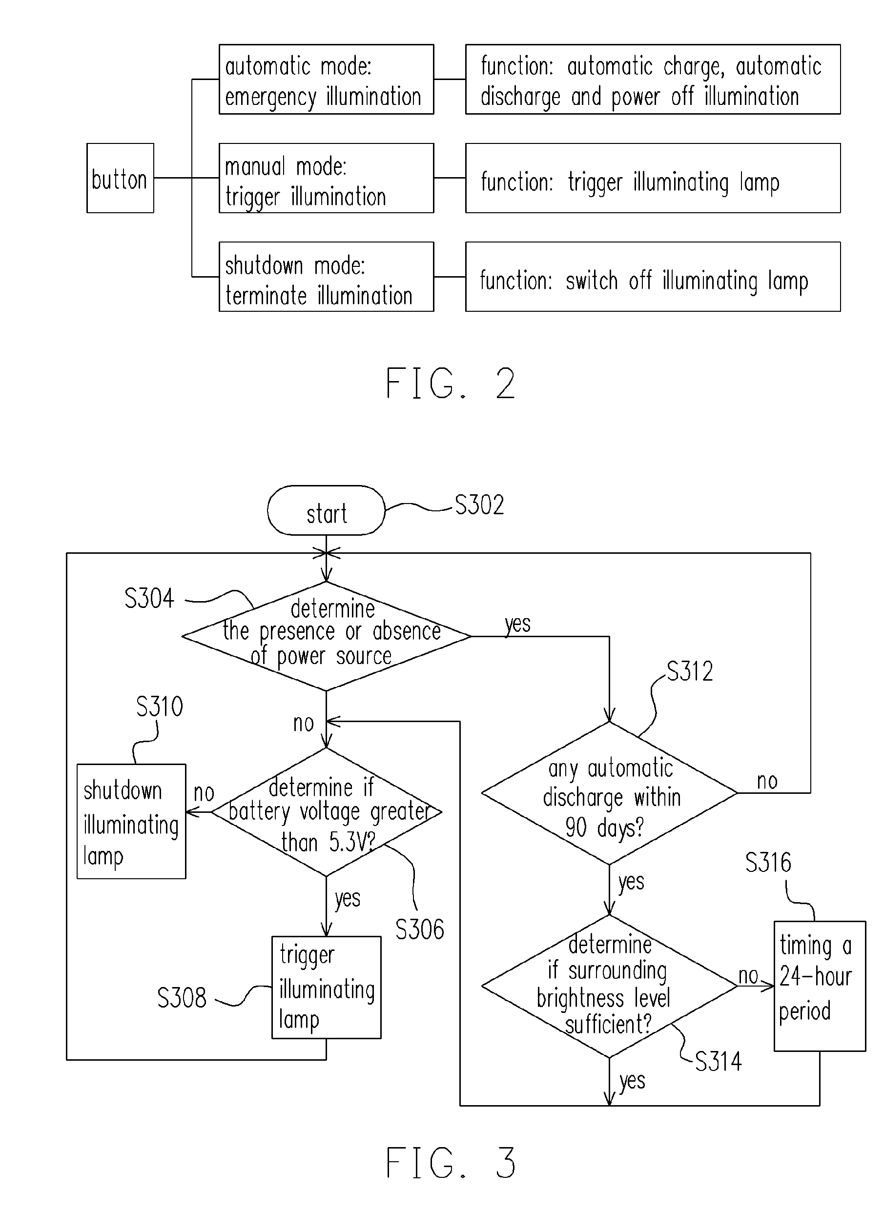
[0030]FIG. 1 is a block diagram showing the circuit layout of an emergency lighting equipment with an automatic charge / discharge and monitoring system according to one preferred embodiment of this invention. The emergency light equipment has an automatic charge / discharge circuit for maintaining a long battery life and another circuit for controlling the size of discharging current from the batter so that the battery can provide power to the lighting equipment longer. In addition, a self-diagnostic circuit is installed to detect any faulty condition in the battery and issue a warning signal when the battery is found to be defective.

[0031]As shown in FIG. 1, the emergency lighting equipment 100 compris...


PUM


Abstract

An emergency lighting equipment with an automatic charge / discharge and monitoring system is provided. The emergency lighting equipment comprises an operating mode control circuit, a rectify / voltage-divide and voltage regulation circuit, a main control unit, an illuminating apparatus and a battery. A battery discharge operating is initiated when the main control unit detects the passage of a preset period without any battery discharge operation. The main control unit also terminates a battery discharging operation when the discharge operation is completed and terminates a battery charging operation after the battery has been float-charged for a preset period of time. The emergency lighting equipment may include a battery state inspection circuit for issuing a warning signal when the battery is found to be defective.

Description

CROSS REFERENCE TO RELATED APPLICATIONS[0001]This application claims the priority benefit of Taiwan application serial no. 92105457, filed on Mar. 13, 2003.BACKGROUND OF INVENTION[0002]1. Field of Invention[0003]The present invention relates to an emergency lighting equipment and charge / discharge method. More particularly, the present invention relates to an emergency lighting equipment with automatic charge / discharge and monitoring system.[0004]2. Description of Related Art[0005]Emergency lighting equipment is an electrical appliance with a long history. The equipment provides some form of illumination to prevent accidents from happening when normal power is suddenly cut. Although most emergency lighting systems currently in the market have had many improvements, some problems including effective working life, damage warning and aesthetic appeal still need to be addressed.[0006]At present, most emergency lighting systems on sale in the market have a working life of only one to two ...

Claims


Application Information

Patent Timeline
Patent Type & Authority Patents(United States)
IPC IPC(8): H02J7/00H02J7/04H02J9/06
CPCH02J7/0029H02J9/065H02J7/045H02J7/0047H02J7/04H02J7/00302H02J7/00306H02J7/007182
Inventor CHEN, SHIH-CHANGCHEN, TSAIR RONG
Owner CASHIDO
Why Eureka
Try Eureka