Magnetic damping for MEMS rotational devices

Inactive Publication Date: 2006-05-02
LUMENTUM OPERATIONS LLC
View PDF10 Cites 5 Cited by
  • Summary
  • Abstract
  • Description
  • Claims
  • Application Information

AI Technical Summary

Benefits of technology

[0011]One aspect of still yet another preferred embodiment of the present invention relates to a method for increasing magnetic damping of a MEMS rotational device including the steps of placing

Problems solved by technology

In many microelectromechanical (MEMS) systems, the primary source of damping is air damping, which may be insufficient with systems with relatively large air gaps.
Under-damped MEMS can lead to long settling times and make closed loop control challenging.
The introduction of fluids can lead to over-damped MEMS.
However, these prior art solutions typically cause hysteresis, an undesirable result bringing about uncertainty of the MEMS angular position.
However, this prior art solution presents no viable solution for a rotating MEMS device.
Many MEMS devices do not have sufficient air damping to achieve a low Q, hence there is a need for a method to introduce additional damping without adding hysteresis or fluids.
Fluids can contaminate a MEMS device and add to the cost and complexity of packaging.
Furthermore, variations in fluid properties can defocus an optical beam and cause insertion loss.

Method used


Image

  • Magnetic damping for MEMS rotational devices
  • Magnetic damping for MEMS rotational devices
  • Magnetic damping for MEMS rotational devices

Examples


Embodiment Construction

[0031]Reference will now be made in detail to the present preferred embodiments of the invention, examples of which are illustrated in the accompanying drawings. Wherever possible, the same reference numbers will be used throughout the drawings to refer to the same or like parts.

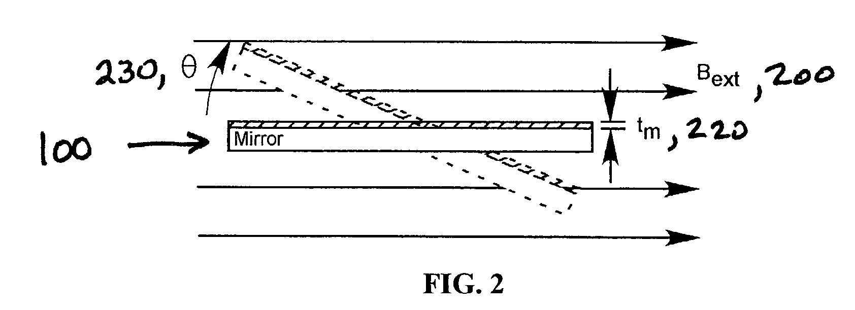
[0032]Several preferred embodiments of the present invention showing the effectiveness of magnetic damping for the plate rotating in a high magnetic field gradient will be described and analyzed infra as follows: (1) a conductive plate rotating about a single axis in a uniform magnetic field; (2) a conductive plate rotating about two axes in a high magnetic field gradient region; and (3) a conductive rectangular plate rotating in a magnetic field.

Plate Rotating about a Single Axis in a Uniform Magnetic Field

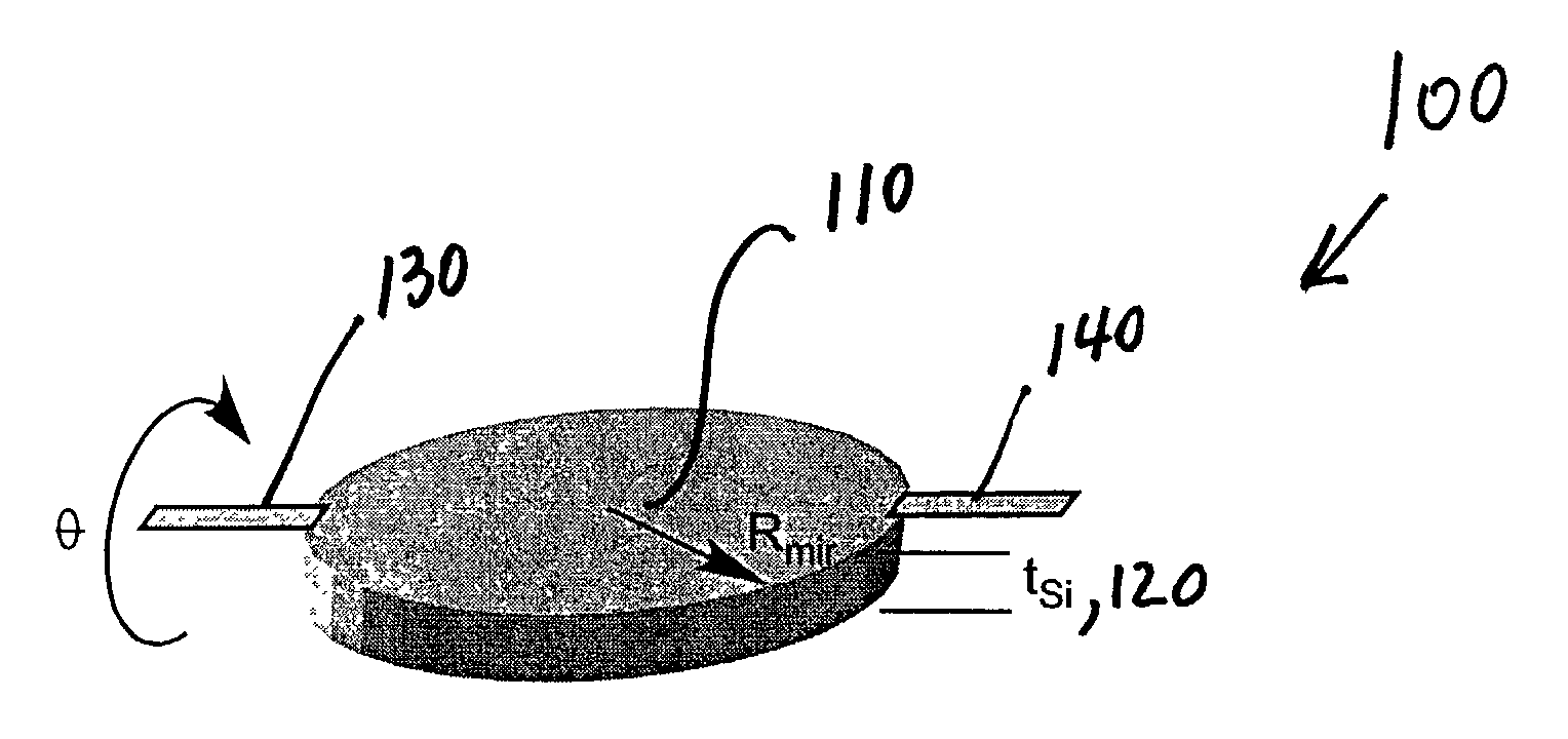
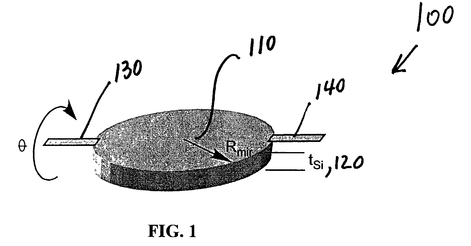
[0033]Referring now to FIG. 1 a circular mirror 100 is shown in accordance with a preferred embodiment of the present invention having a radius Rmir 110 and a thickness tSi 120. Circular mirror 100 rotate...


PUM


Abstract

The effectiveness of magnetic damping on a MEMS device rotating in a high magnetic field or field gradient is described and analyzed for three preferred embodiments: (1) a conductive plate rotating about a single axis in a uniform magnetic field; (2) a conductive plate rotating about two axes in a high magnetic field gradient region; and (3) a conductive rectangular plate rotating in a magnetic field. Control of a rotational MEMS device such as a mirror necessitates fast response and settling times. Optimal response is achieved by reducing the mechanical quality factor (Q) close to one (1). Magnetic damping is found to be an effective means of reducing the Q factor of MEMS rotating mirrors without introducing hysteresis, narrow gaps or fluids. Methods to reduce the Q factor include reducing mirror mass and moment of inertia, increasing the conductive layer thickness, and increasing ∂ϕ∂θor magnetic flux density variation as a function of angle.

Description

FIELD OF THE INVENTION[0001]This invention relates to magnetic damping, and in particular to magnetic damping of MEMS rotational devices.BACKGROUND OF THE INVENTION[0002]Damping has been identified as an important principle for micromechanical devices to help reduce errors and speed settling while improving stability. Micromechanical devices can be fabricated with purely elastic supports, resulting in a classic spring-mass-damper system. In many microelectromechanical (MEMS) systems, the primary source of damping is air damping, which may be insufficient with systems with relatively large air gaps. Under-damped MEMS can lead to long settling times and make closed loop control challenging. The introduction of fluids can lead to over-damped MEMS.[0003]Several known damping mechanisms exist such as fluid damping and mechanical friction. Prior art solutions to perfect damping in MEMS mirrors have used soft metals, such as gold, on the springs or the supports, while other solutions have ...

Claims


Application Information

Patent Timeline
IPC IPC(8): G02B26/00G02B26/08
CPCG02B26/0841
Inventor BERNSTEIN, JONATHAN JAY
Owner LUMENTUM OPERATIONS LLC
Why Eureka
Try Eureka