Behind-the-ear housing functioning as a switch

Inactive Publication Date: 2006-05-02
SONOVA AG
View PDF12 Cites 12 Cited by
  • Summary
  • Abstract
  • Description
  • Claims
  • Application Information

AI Technical Summary

Benefits of technology

[0004]It is therefore an objective of this invention to introduce a system for operating hearing aids whereby for instance elderly persons or even someone wearing gloves with consequently reduced dexterity can operate a hearing aid, to the extent manually possible, in simple fashion.

Problems solved by technology

In view of the small dimensions of the device the control elements are quite tiny, requiring ultradexterous fingers for operating these elements.
Since wearers of hearing aids are usually members of the older generation, it is often very difficult for them to manipulate such microcontrols.
While a remote control unit can certainly overcome that problem, it is not always viewed as a desirable solution, and when the remote is misplaced as can easily happen, operation of the device is rendered altogether impossible.

Method used


Image

  • Behind-the-ear housing functioning as a switch
  • Behind-the-ear housing functioning as a switch

Examples


Embodiment Construction

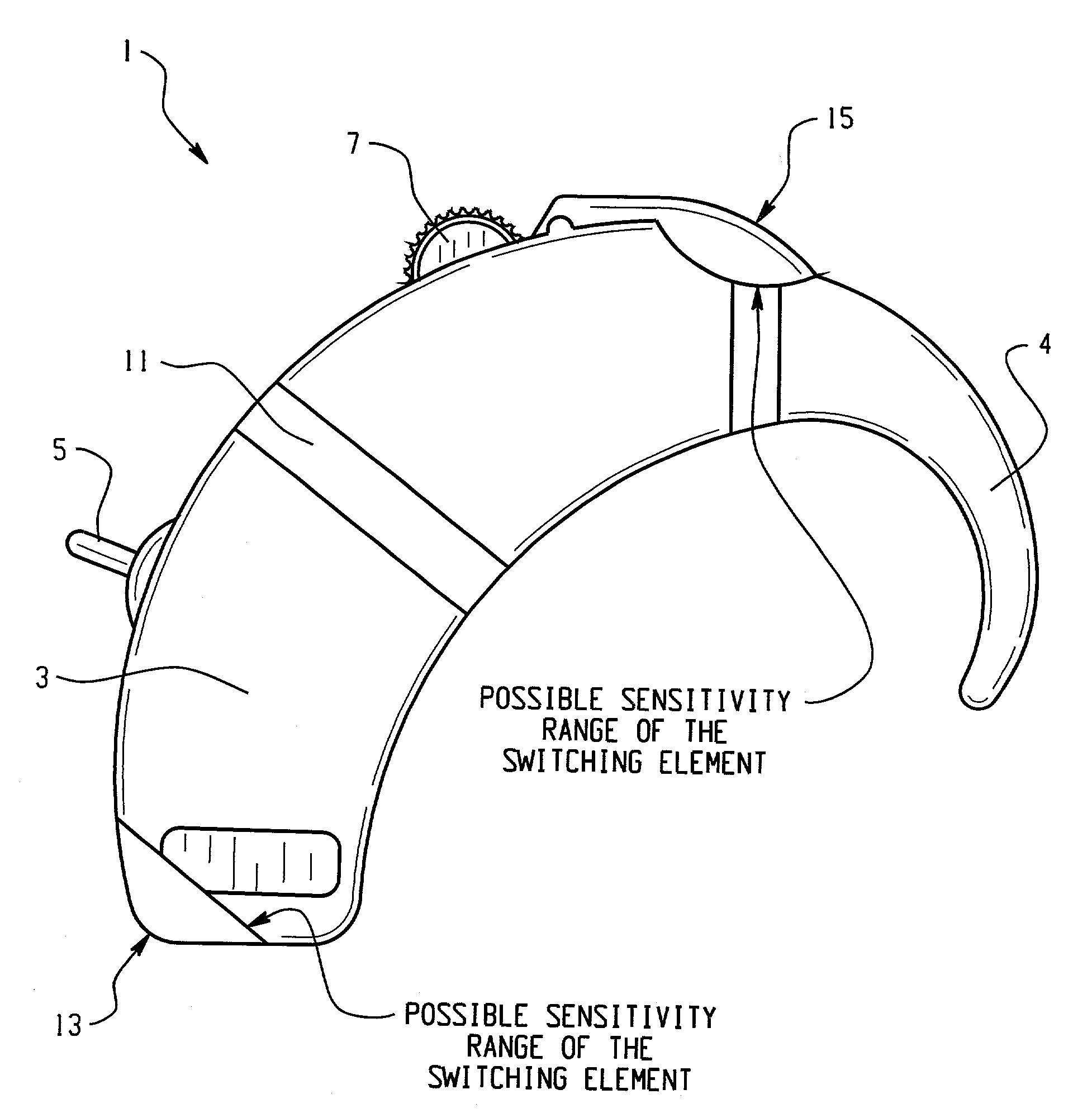
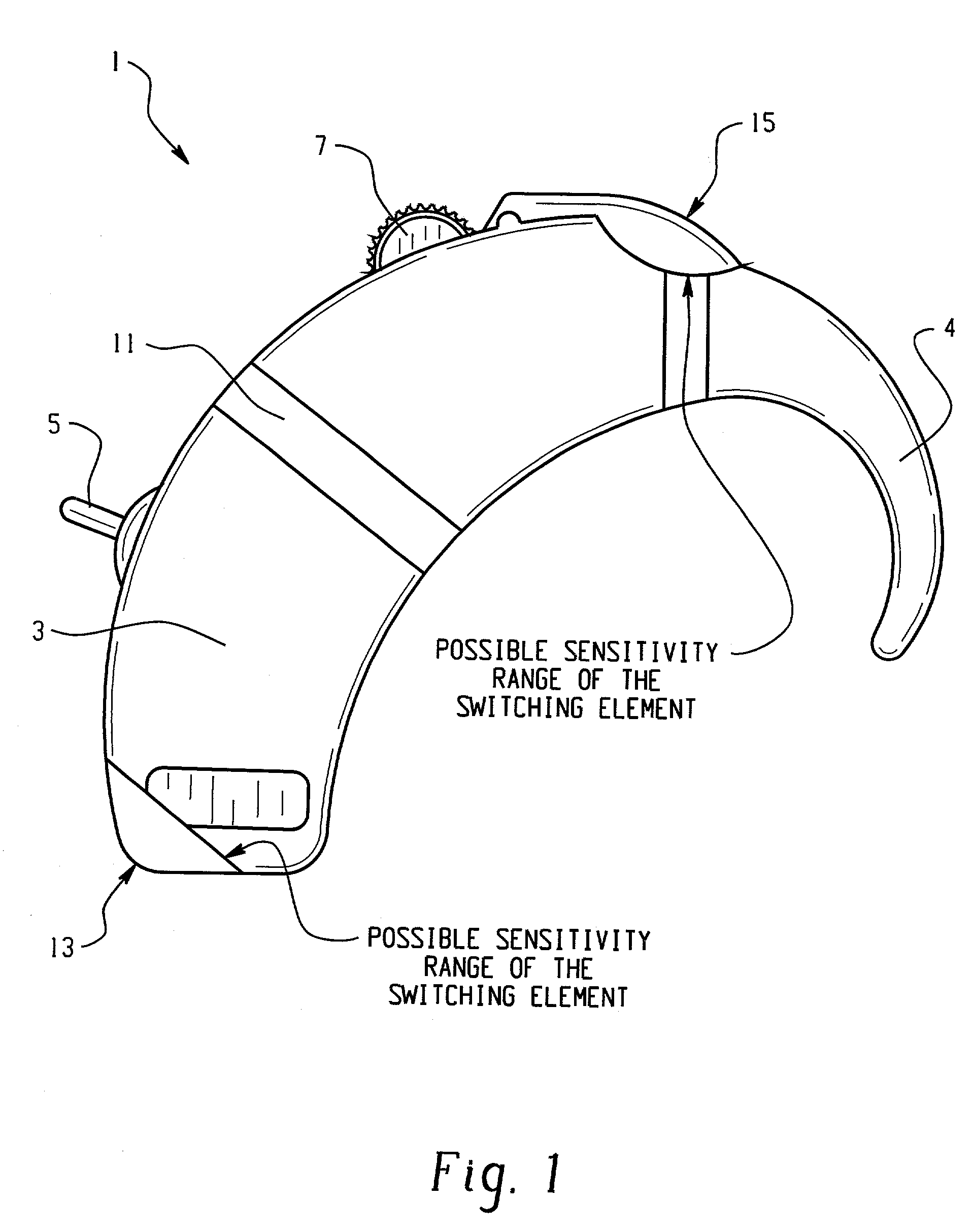
[0015]The hearing aid 1 shown in FIG. 1 encompasses a so-called behind-the-ear housing primarily including an inflexible, rigid housing section 3 and terminal bracket 4 designed to permit positioning of the hearing aid behind the ear. For the operation of the hearing aid the housing is equipped with different switching elements such as an on / off switch 5 or a volume control 7. Because of the ultra-small dimensions of these two switching elements it is evident that operating the hearing aid depicted in FIG. 1 is possible only if the wearer has the necessary micromotorial dexterity, failing which it would be difficult at best to operate these controls.

[0016]This invention therefore proposes the positioning of a bendable or resiliently deformable section 11 in the central area of the housing 3, which can be bent or compressed by applying pressure at the two actuating pressure points 13 and 15. For example, the index finger may push against pressure point 15, the thumb against point 13....


PUM


Abstract

A housing (3) for electrical and / or electronic microdevices, in particular hearing aids (1), encompassing at least one switchable element or switching circuit system, is provided with a pressure-sensitive, bendable and / or elastic section (11). That section is functionally connected to the said switching element or circuit system in such fashion that applying pressure on the housing or bending or deforming the elastic section (11) triggers a switching operation of the switching element or circuit system.

Description

FIELD OF THE INVENTION[0001]This invention relates to a housing for electrical and electronic microdevices, containing at least one switchable element or switching circuit system, to a hearing aid with a housing, and to a method for operating a hearing aid.BACKGROUND OF THE INVENTION[0002]When on a hearing aid electrical or acoustic settings are to be changed, this is accomplished by means of controls on the device or by a remote control. These control elements are switches, potentiometers and the like, collectively referred to as control elements.[0003]In view of the small dimensions of the device the control elements are quite tiny, requiring ultradexterous fingers for operating these elements. Since wearers of hearing aids are usually members of the older generation, it is often very difficult for them to manipulate such microcontrols. While a remote control unit can certainly overcome that problem, it is not always viewed as a desirable solution, and when the remote is misplaced...

Claims


Application Information

Patent Timeline
IPC IPC(8): H04R25/00H01H9/06
CPCH04R25/65H01H9/06H01H2003/007H01H2011/0081H04R25/658H04R2225/021H04R2225/61H01H2300/004H04R25/603
Inventor WAGNER, JOSEFOERTLI, DANIEL
Owner SONOVA AG
Why Eureka
Try Eureka